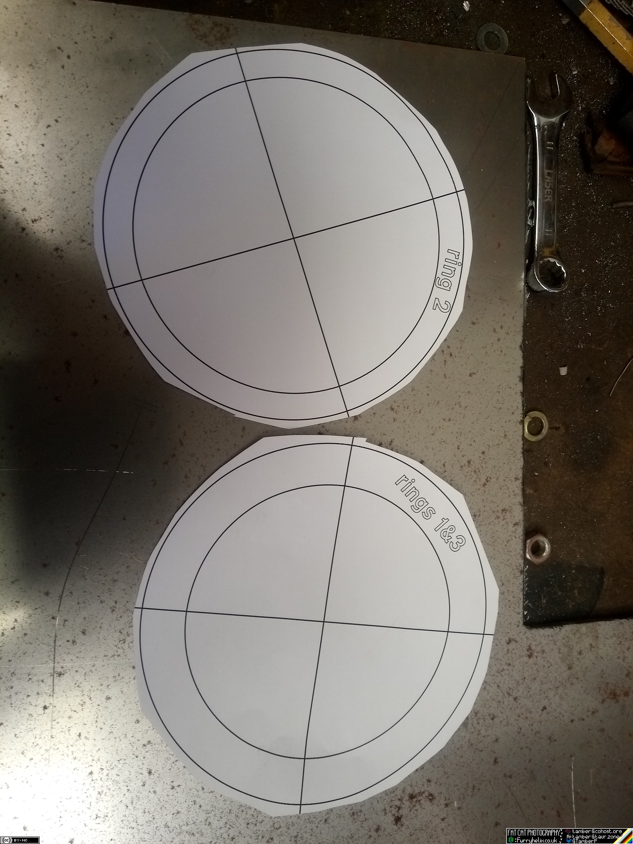
 Templates drawn. I would have preferred to have these cut by cnc
plasma, or something, but I haven't yet gotten myself to the point I
can make up and send out a drawing for someone else to cut it. So how
do we make those?
Templates drawn. I would have preferred to have these cut by cnc
plasma, or something, but I haven't yet gotten myself to the point I
can make up and send out a drawing for someone else to cut it. So how
do we make those?
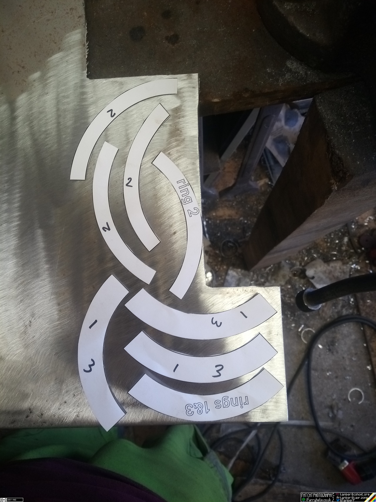

And cue about an hour and a half with the angry grinder, cut-off
wheels, grinding discs and flap-disks; until we get something that
looks a little like so:
And the whole thing will build up in layers thusly:
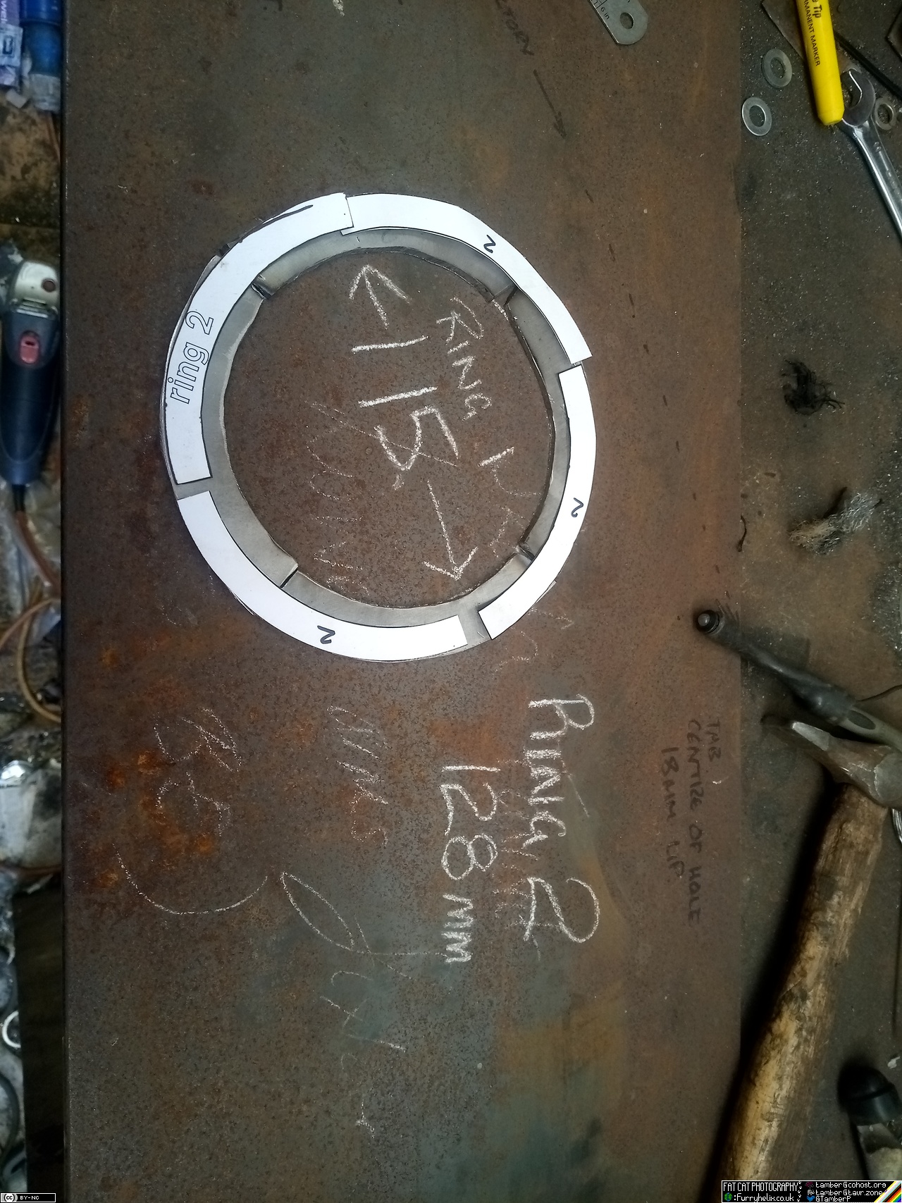
Also noted are dimensions. (Do not use those dimensions. I screwed up the most important one, but hadn't realised it at this point.)
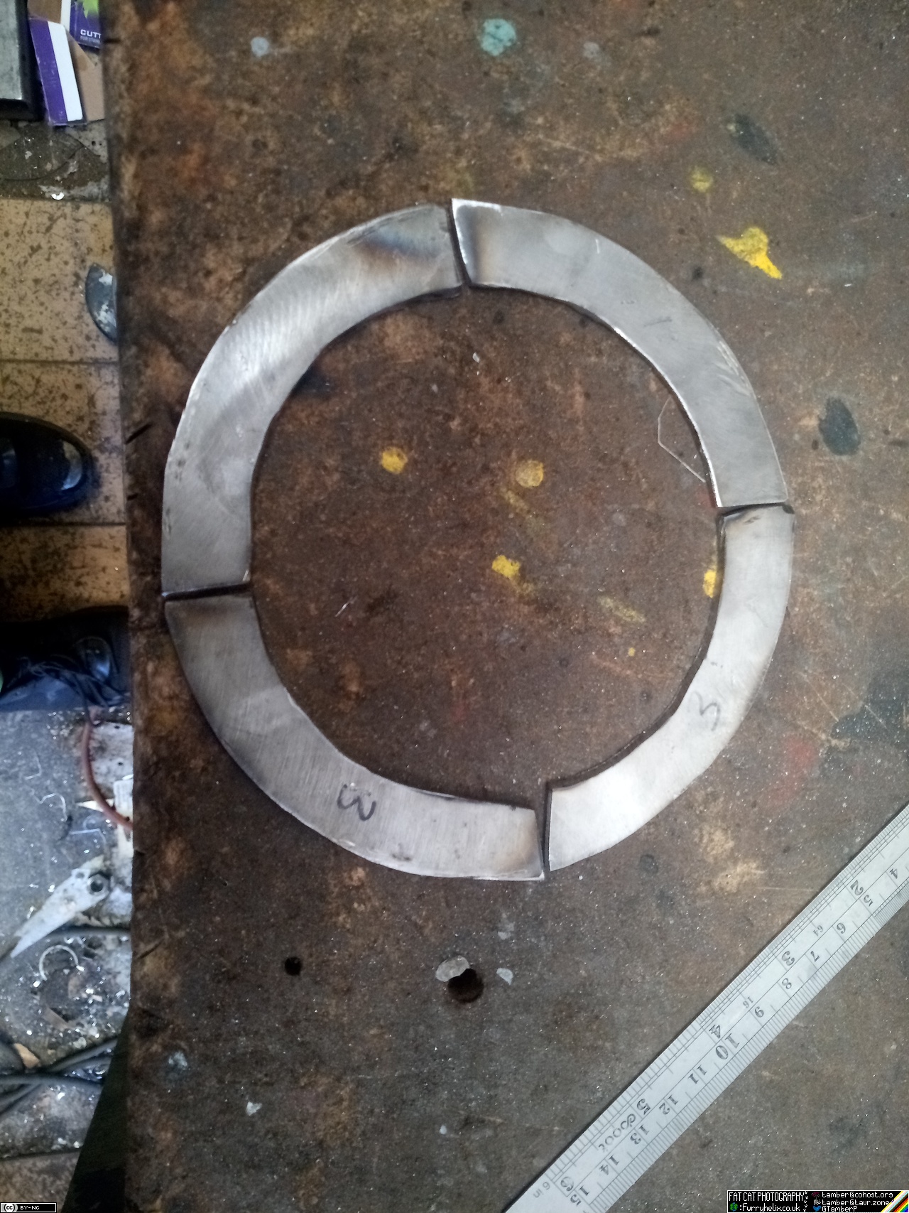
Then, weld the pieces together like so:
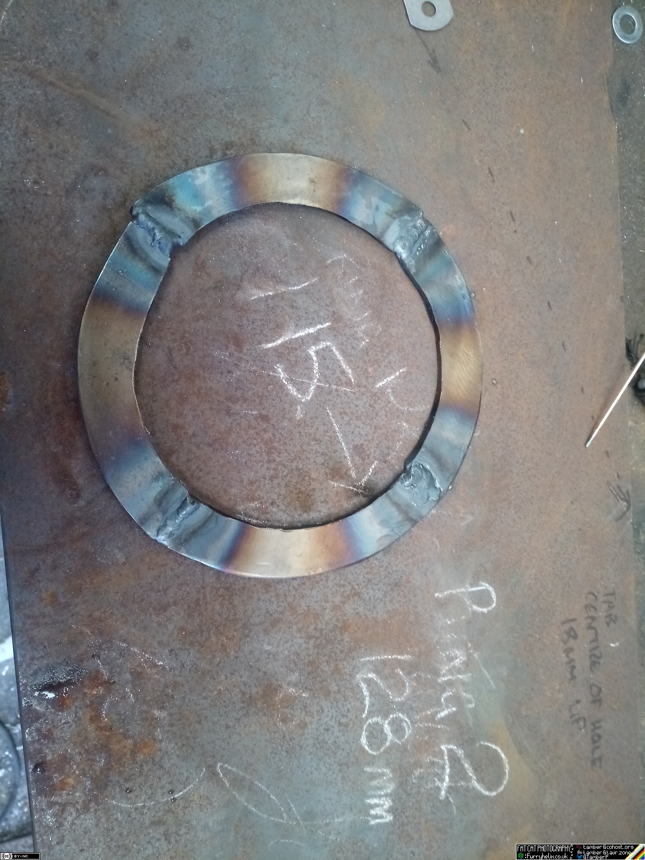 (I still haven't discovered the screw-up.)
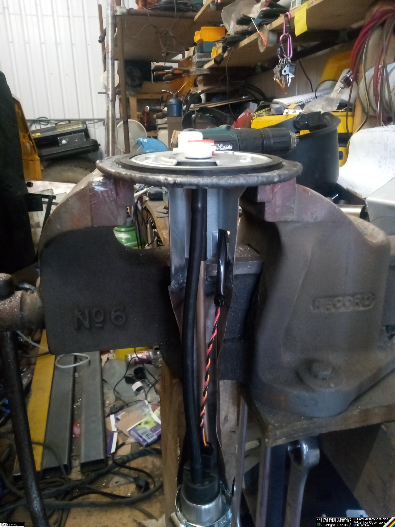
Once that's cooled, carefully tidy-up all the rough edges and whatnot inside until it's a nice smooth circle at 115mm. Then drop the fuel pickup/pump unit through it.
Spend about an hour building the inside edge up with weld, until
you've taken up the 10 mm measuring error. 
Grind all of that flush, and test-fit again!
Next step, repeat the process with layer 2; which it appears I did
manage to measure correctly, at least.
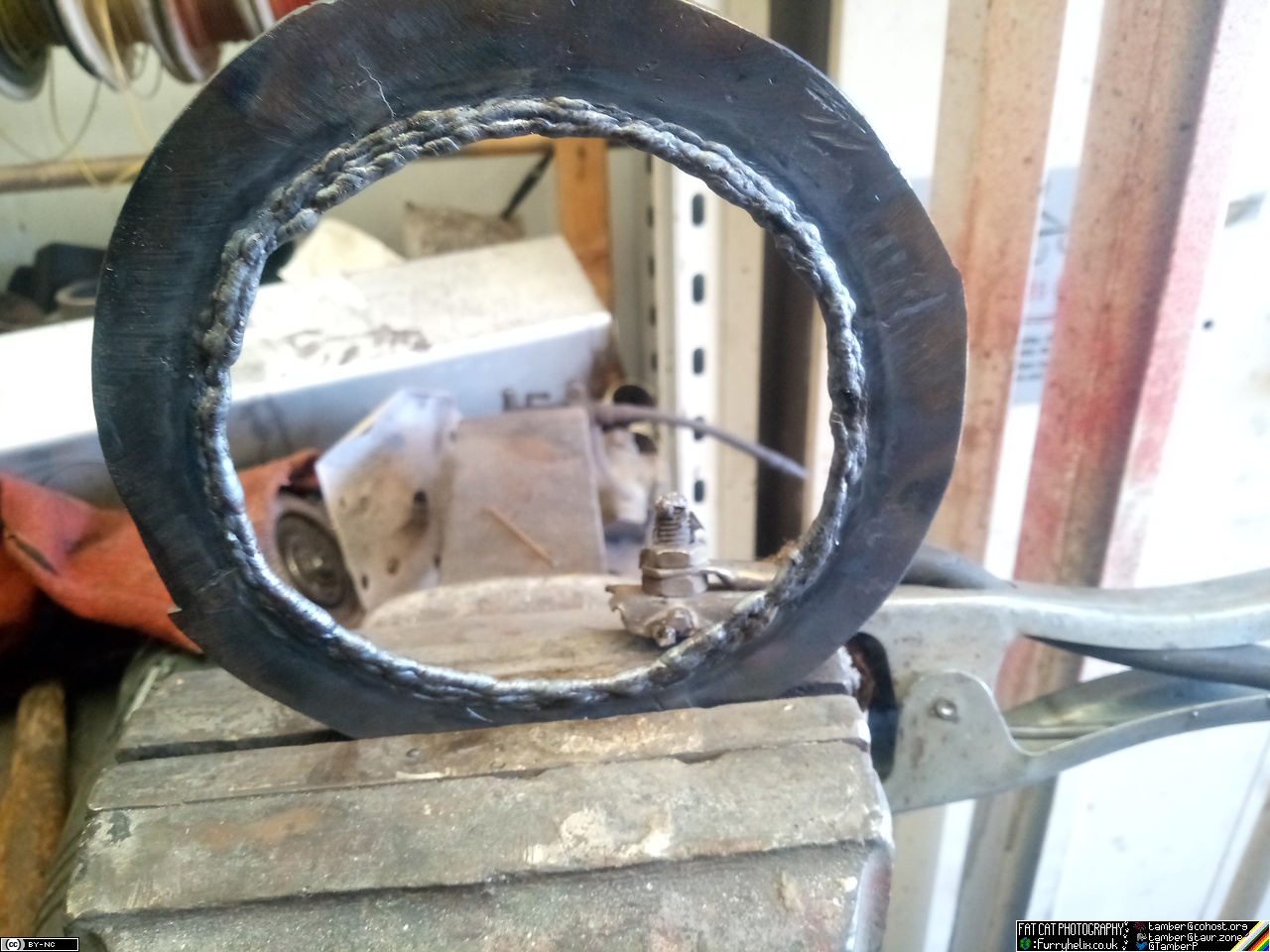
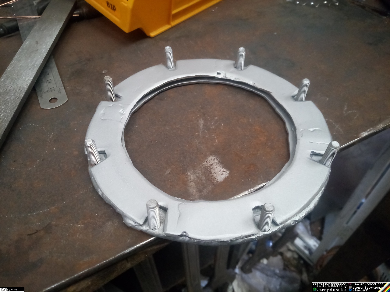
Weld layer 2 on top of layer 1, and that results in... (drumroll please):
Some tidying up with a die-grinder needed to dress the welds back on the inside so that the sender sits in properly, and that's the lower portion done. Layer 3 is identical to layer 1, but is bolted down onto the previous two in order to clamp the pump unit in place. Hopefully I've left myself enough material on the segments for layer 3, that I don't need to build the whole thing up with weld, now that I know about the measurement screw-up.
As for the correct dimensions: - All three layers have a 150mm OD, and are to be made from 4mm thick steel. (I made mine from 3mm, because that's what I had. It should seal fine, but I might not be able to fully seat the plates together by the time it's clamped tight.) - Layers 1 and 3 have a 106mm ID. Layer 2 has a 125mm ID. Bolt-holes added to taste.
Once I'm done messing about with this, I've got to cut a hole in the top of the fuel tank to mount it, which should prove... exciting.
About a week later ...
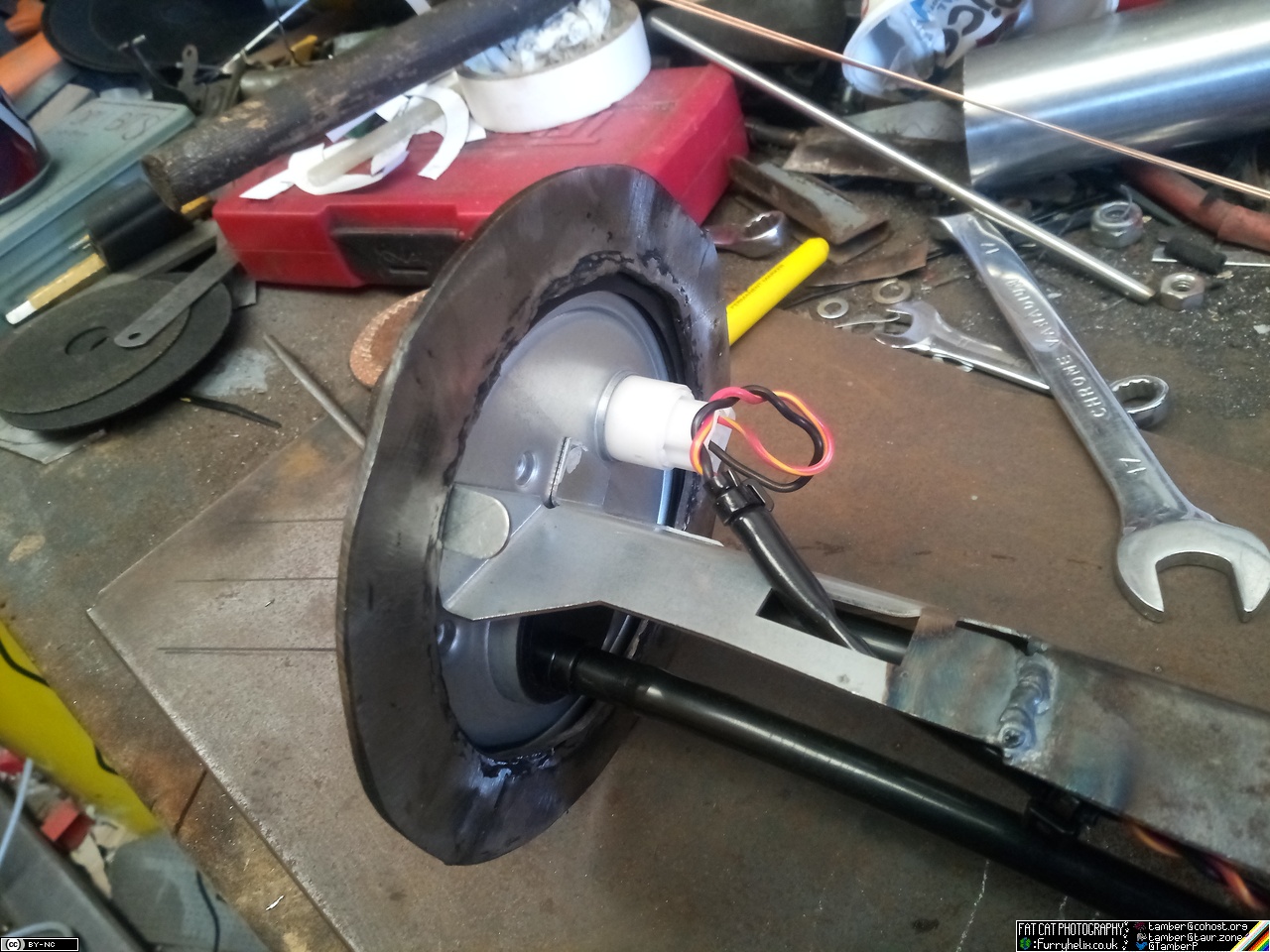
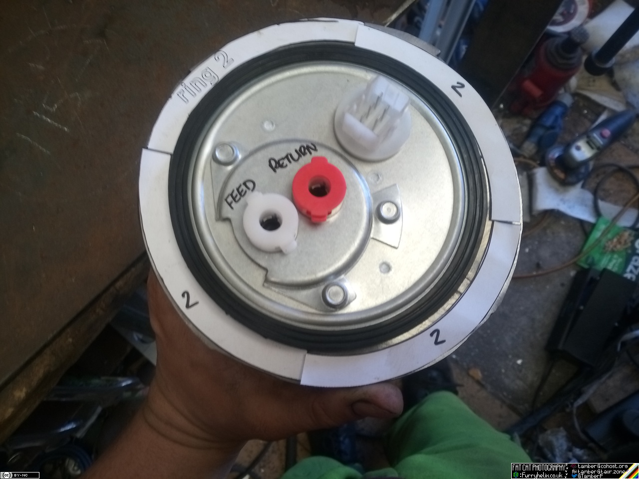
 The completed fuel pump mounting ... thing. I didn't get the alignment
of my hold-down studs absolutely perfect, so I did end up having to
open out the slots slightly in order to get the top ring to fit in any
position. Might've tickled them out a touch further than intended, but
it's nothing that some washers won't fix.
The completed fuel pump mounting ... thing. I didn't get the alignment
of my hold-down studs absolutely perfect, so I did end up having to
open out the slots slightly in order to get the top ring to fit in any
position. Might've tickled them out a touch further than intended, but
it's nothing that some washers won't fix.
I've ordered the big hole-saw for the top of the tank,
too. Soon&trademark; 
Then back onto making the injector hold-down bosses for the other two
runners, and getting them welded in place. Took a little time to get
back in the swing of welding aluminimu, but eventually we get to this
point:
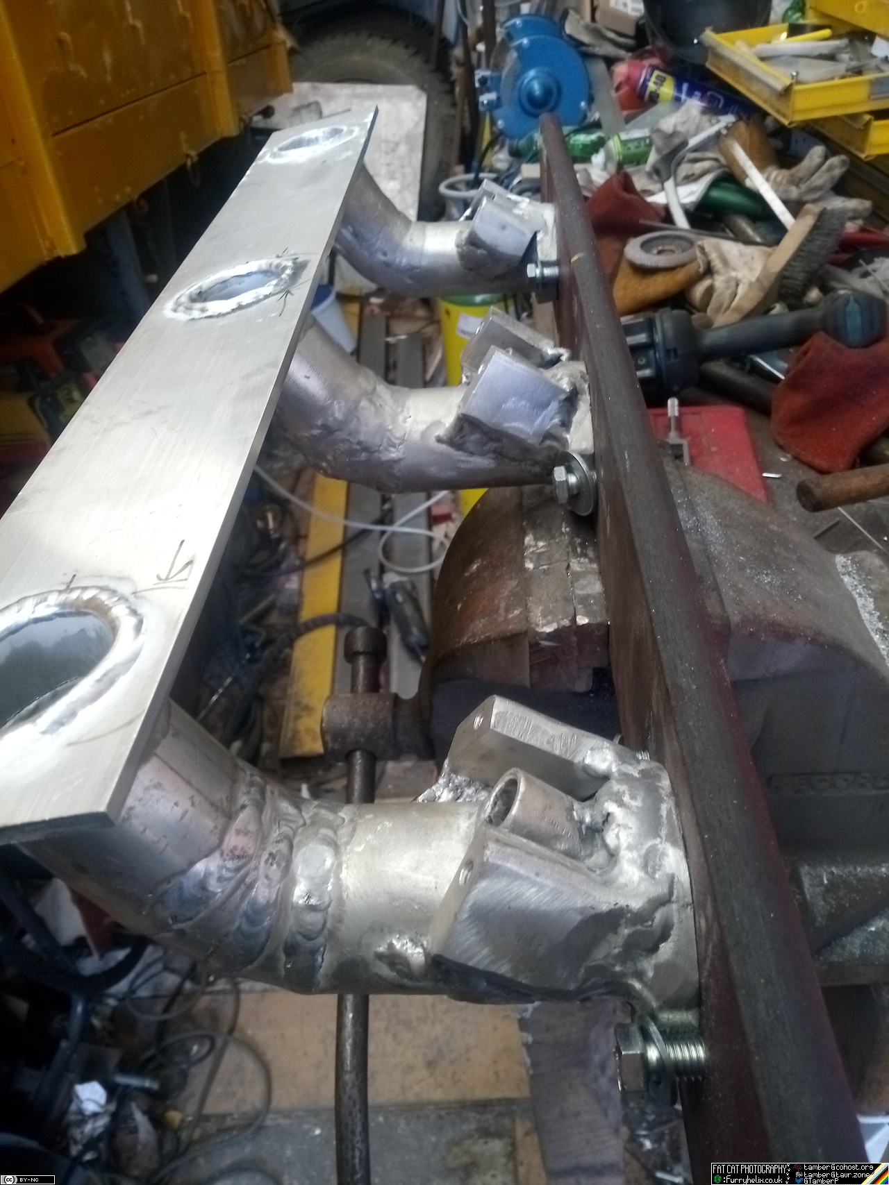
(I have just noticed I forgot to round the corners off the hold-downs on the centre runner, whoops.)
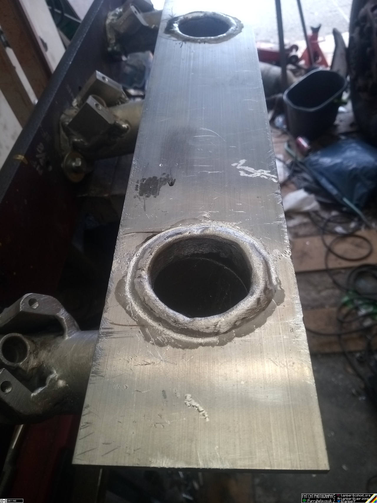
A little die-grinder and file action to round the welds off on the
inside of the manifold -- doing my best to make a nice-ish radius --
and we start to look a little more like:
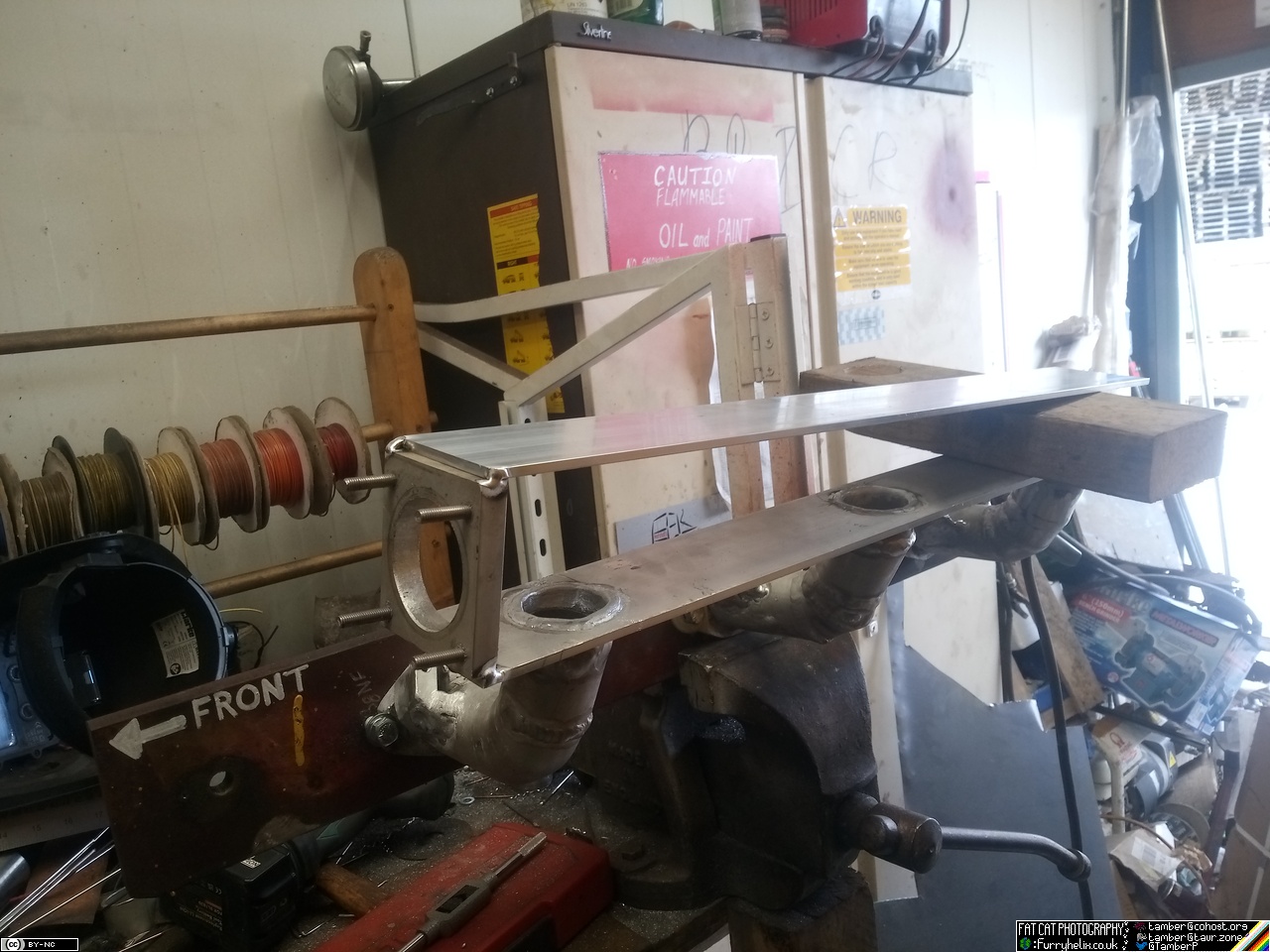
Well, that's looking snazzy, but what sort of overall shape is it
going to take? That should be easy enough to set up, if I space the
back of the plenum up with a block of wood to get it about the right
height, and find the flange with the throttle-body on it...
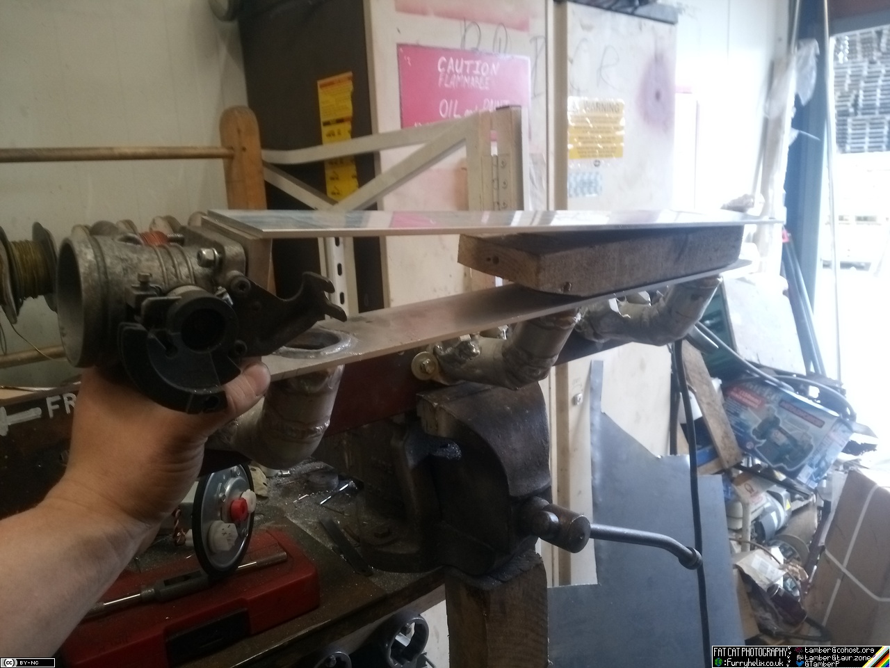 And I think that's looking perfectly acceptable.
 All tacked together.
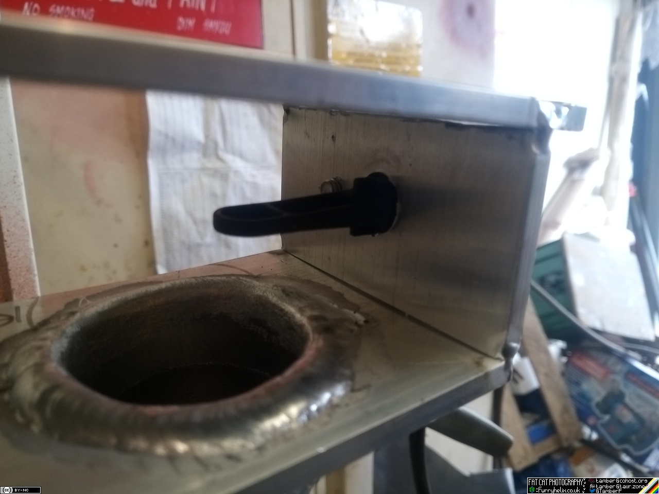
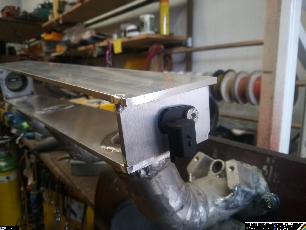
And with the manifold air temp sensor fitted over the cylinder 5 & 6 runner...
Now I'm a little bit annoyed that I stuck the original manifold back
on the other week, because I really want to test-fit this before I
commit to fully welding it! Didn't realise I was going to be struck by
sudden movement on this front, or I might've left it off.  Maybe I'll just
leave it half-done until I've collected more of the fuel-injection
bits; or maybe I'll just measure measure measure until I feel happy
about it, and just weld it up~
Maybe I'll just
leave it half-done until I've collected more of the fuel-injection
bits; or maybe I'll just measure measure measure until I feel happy
about it, and just weld it up~
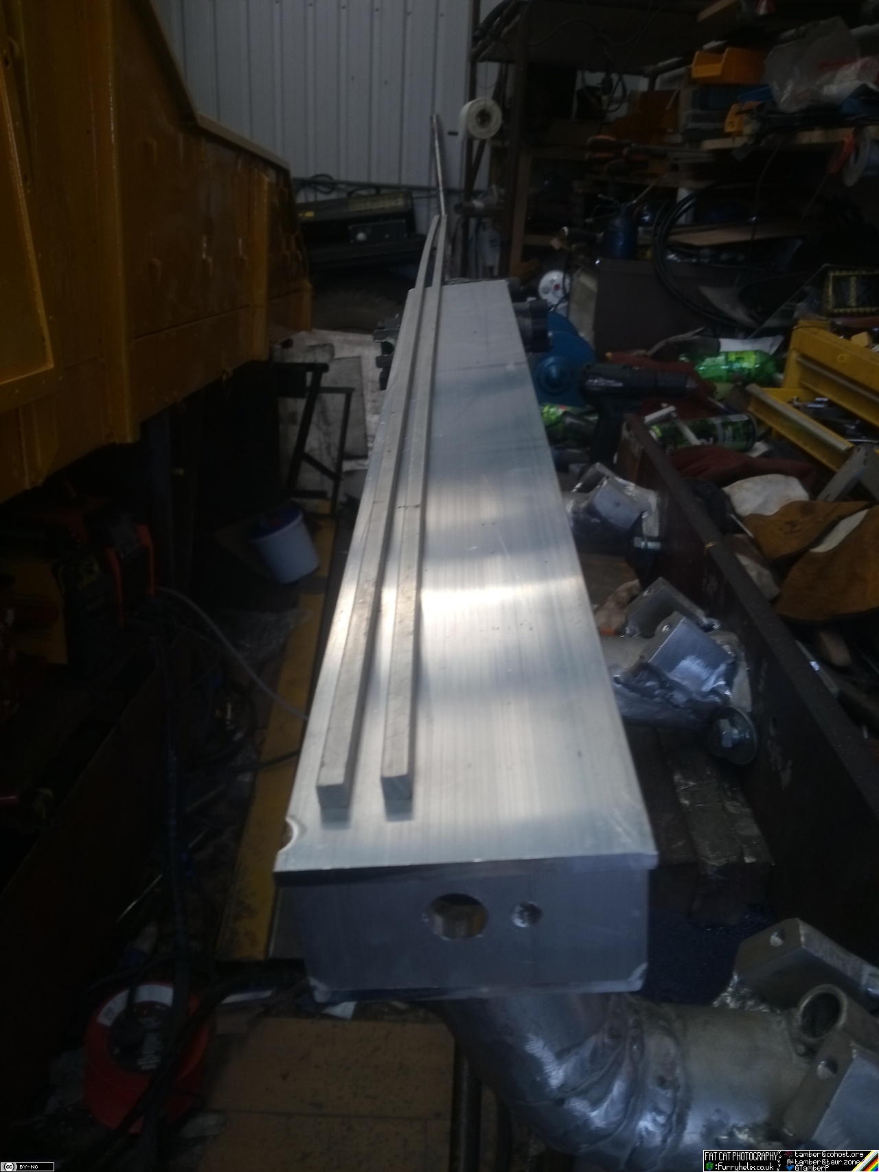 Also, I dug out the little bits of square stock and laid them on top
to see how that looks; I like it, so I'll order up some more of it
along with a few other bits I need, like the plate for the injector
clamps, and whatnot.
Also, I dug out the little bits of square stock and laid them on top
to see how that looks; I like it, so I'll order up some more of it
along with a few other bits I need, like the plate for the injector
clamps, and whatnot.