May 2018
Some kinda-clunky brake-piping happened!
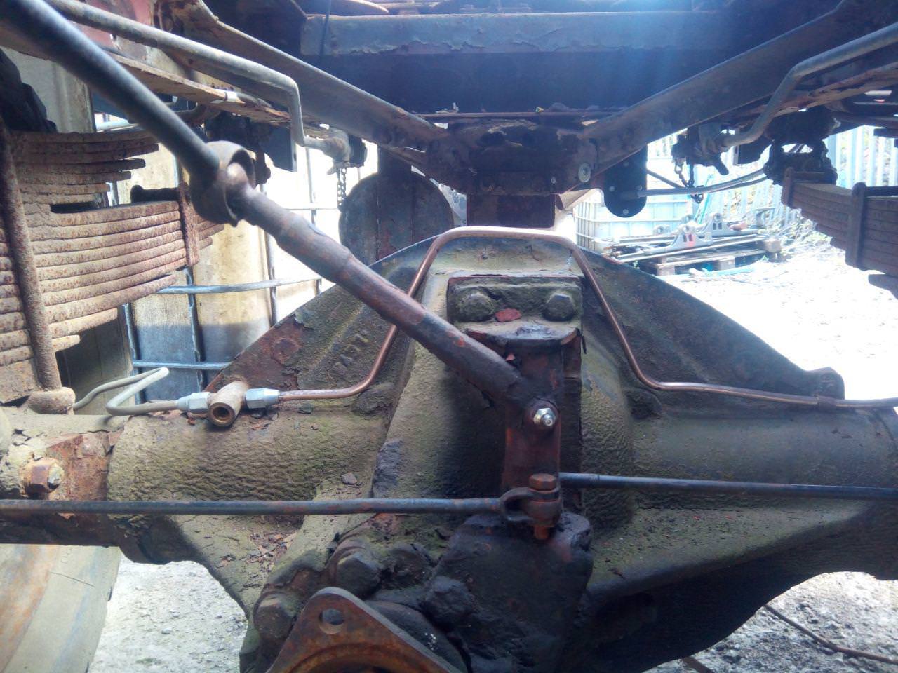
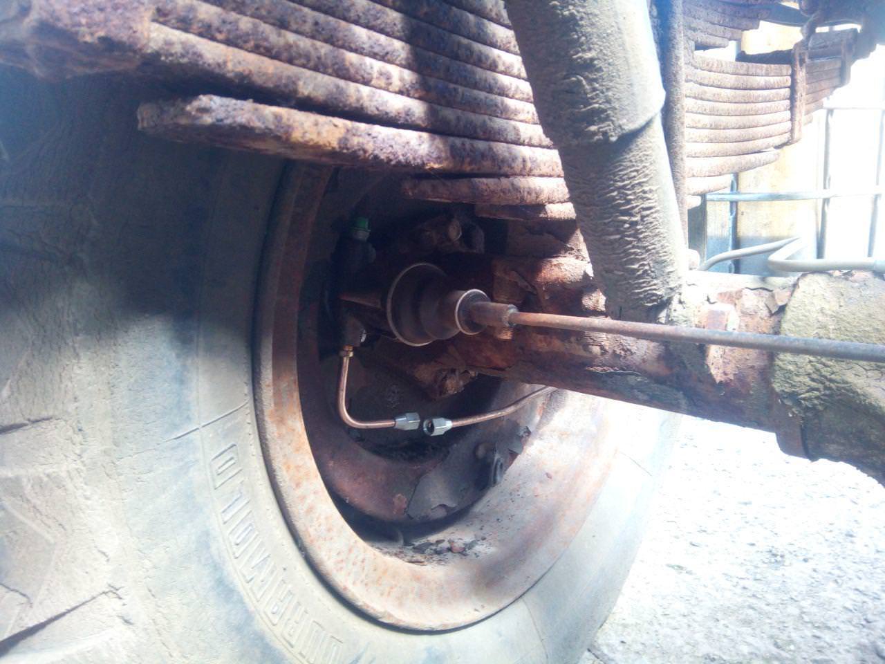
I wasn't really happy with it, especially since I ended up having to join it because I screwed up the last bend. It later gets redone, and most of it gets reused elsewhere anyway. All a learning experience!
While I was stood around staring at the truck in bewilderment -- this happens a lot, I'll find myself sitting there staring into space thinking about nothing in particular -- I kinda decided that I wanted to clean up a bit of the paintwork. So I did!
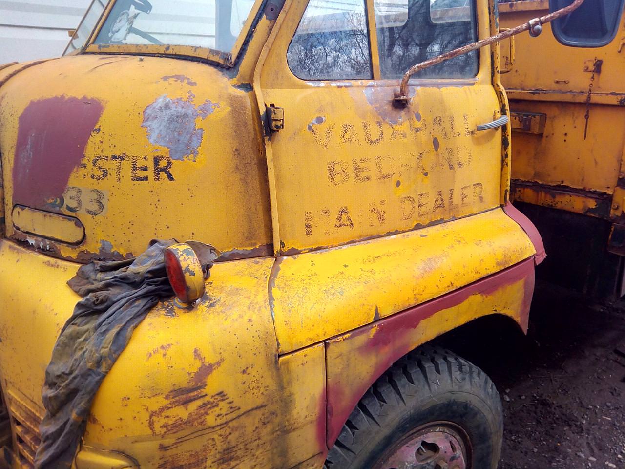
And then I went to prime over some patches where the paint had flaked off, which I got carried away with and resulted in:
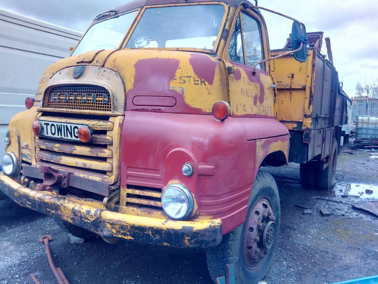
Then I popped the grille off, and picked off all the curled-up paint. Y'know, while there was still a grille left. Thankfully, it turned out to be pretty solid.
Wire wheel, rust-convert, prime, refite.
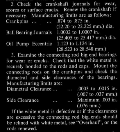
Also fitted a new beacon on the roof, which meant I got to look at how bad the roof is, again. And with a new beacon, I needed a switch for it. Well, that and some other stuff, so I made up a small panel...
Illuminated toggle switches; three amber, one blue. I was worried, at the time, that the blue one for fog lights might be a bit too bright; bu tit turned out that it's high enoug hup that it's not burning holes in your eyes while you'd be driving.
Early June 2018
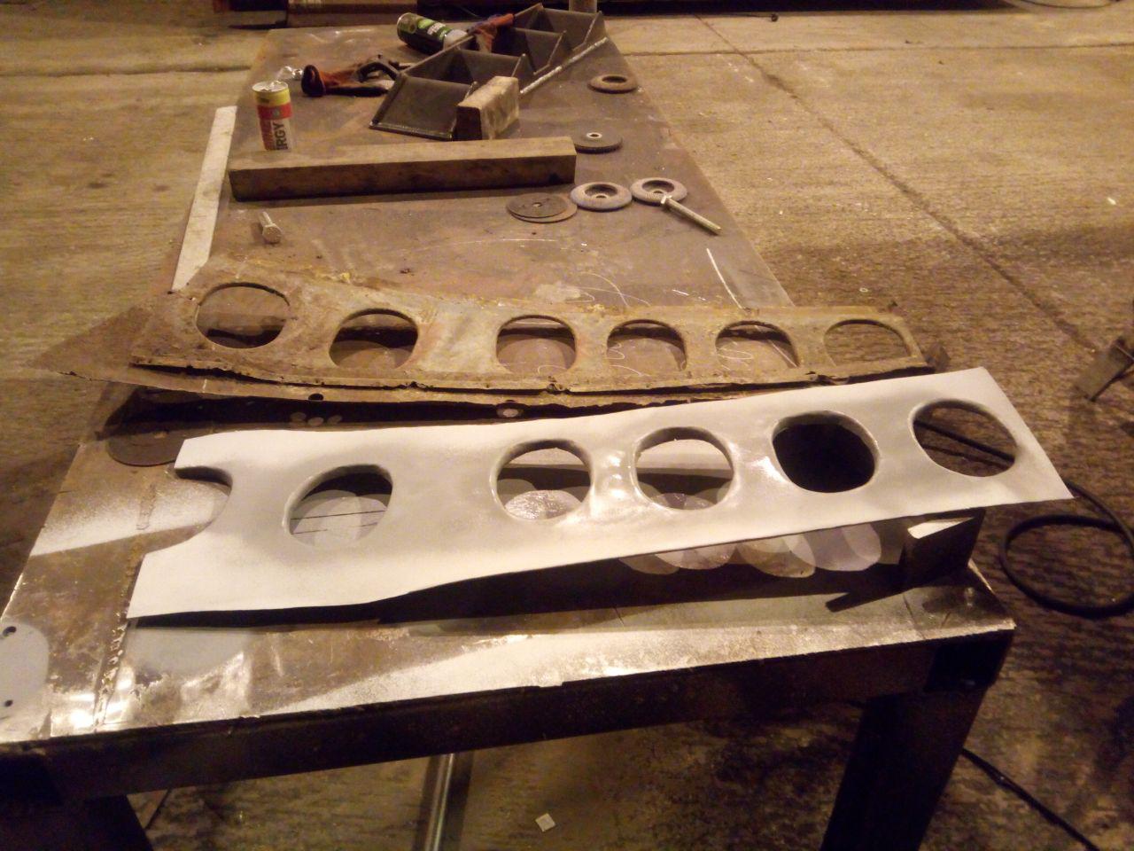
Well, since I'd played scrap-man earlier on, it was perhaps time to start putting some metal back in.

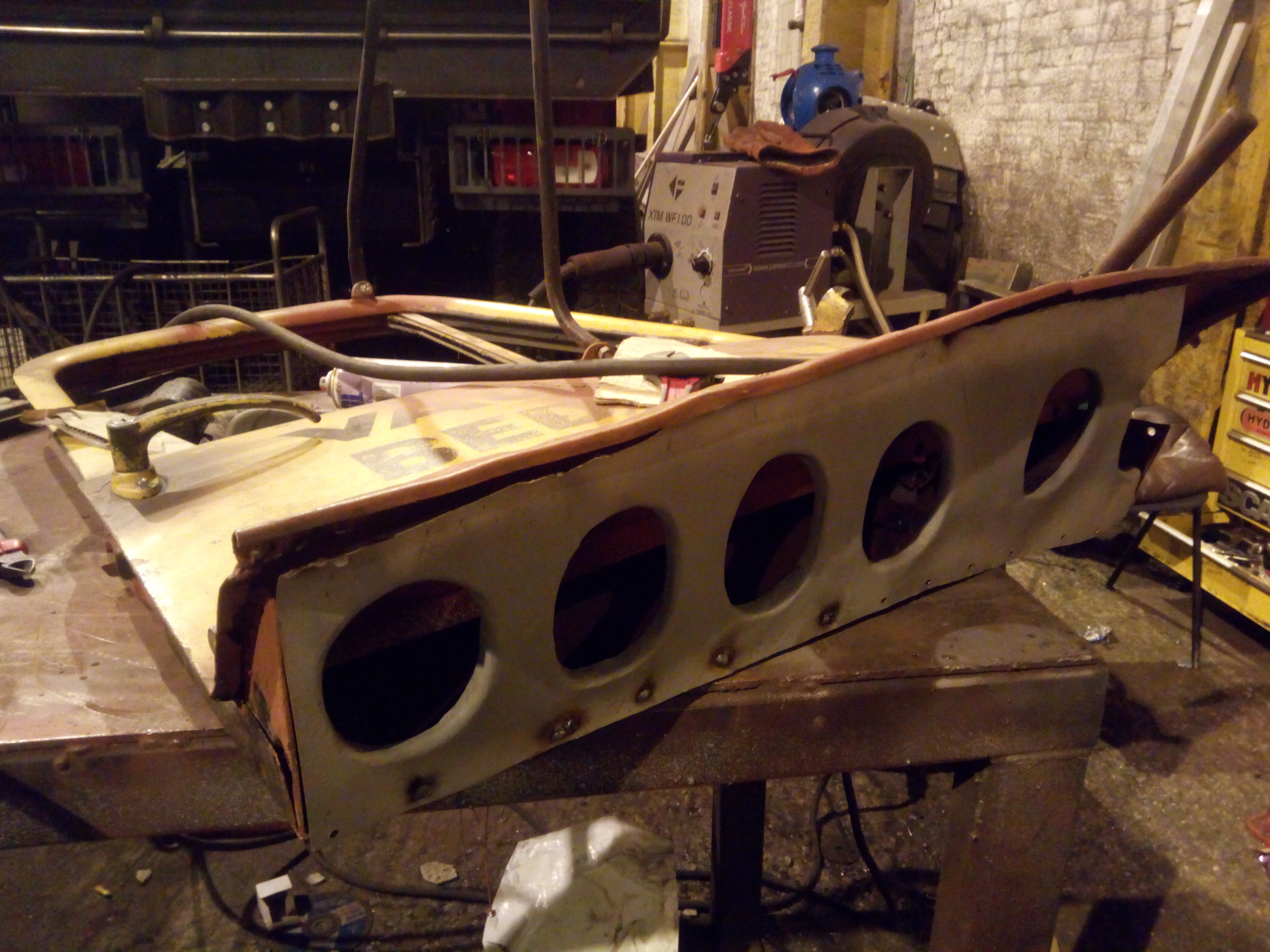
Yeah, that'll do nicely. Let's see where it's going.
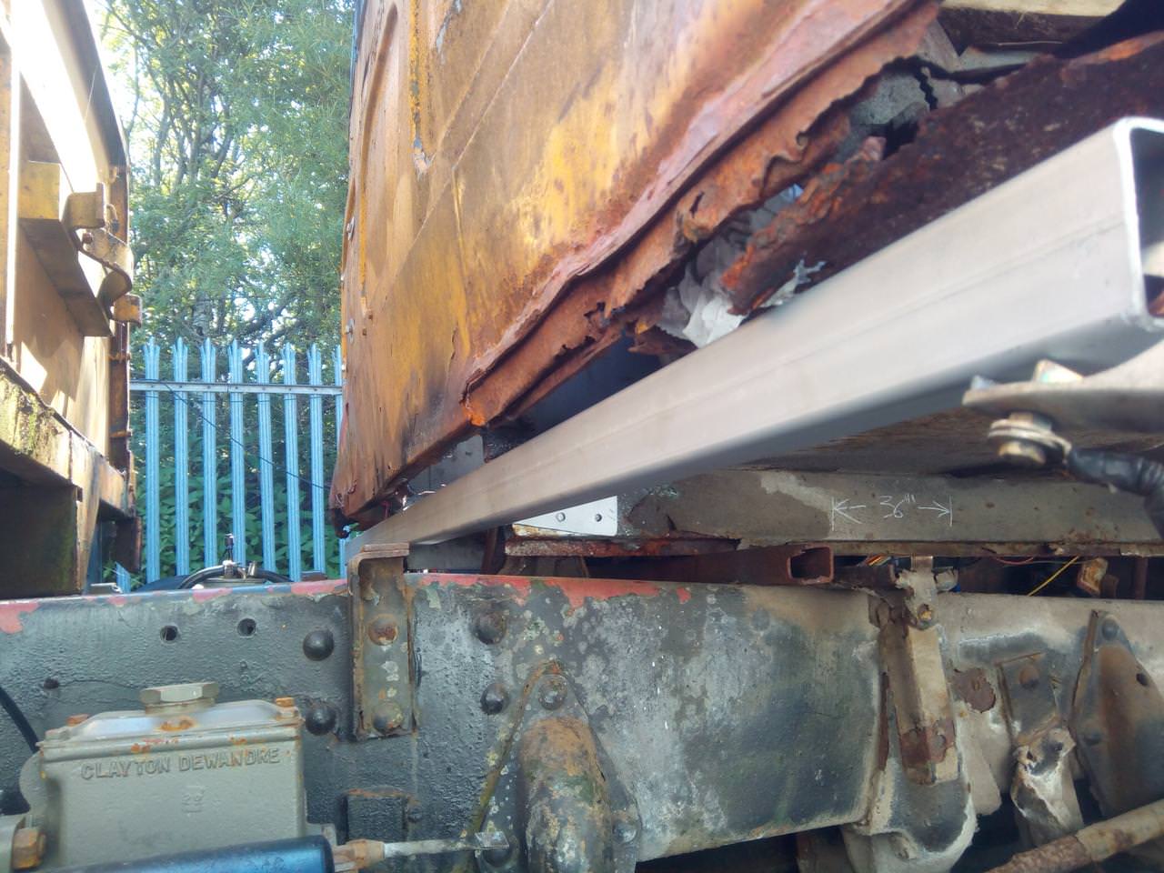
Looks right to me, time to tack it into place. Cue the sparks and cursing.
You'll notice that I'm still using a stick welder, at this point. It does not result in the prettiest welds on stuff like this, but it's good enough for now. (I have now got a small MIG welder.)
Late June 2018
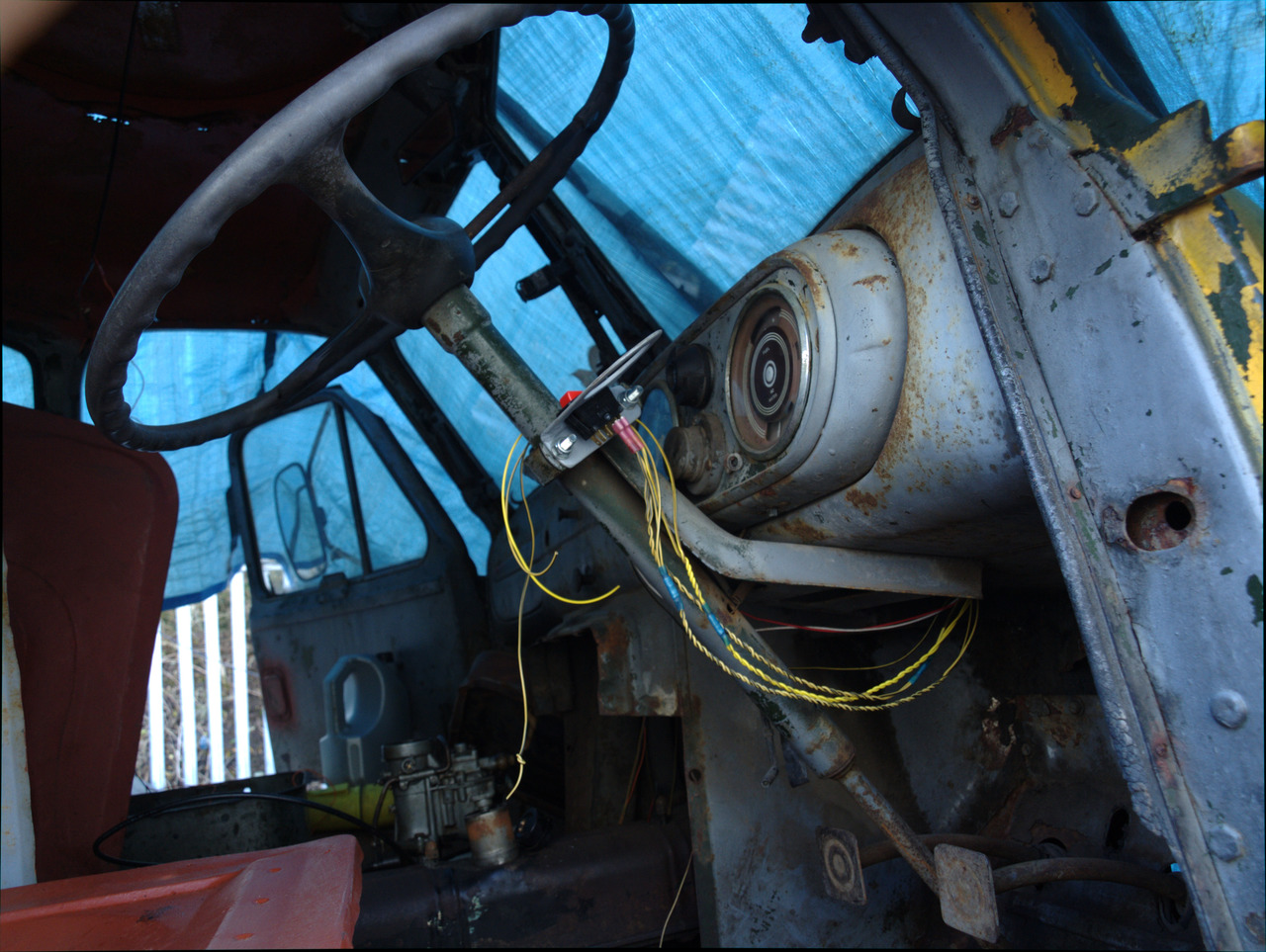
Tried to persuade myself that fitting an overkill bracket for a beacon counts as progress. Meet... The Überbräcket.
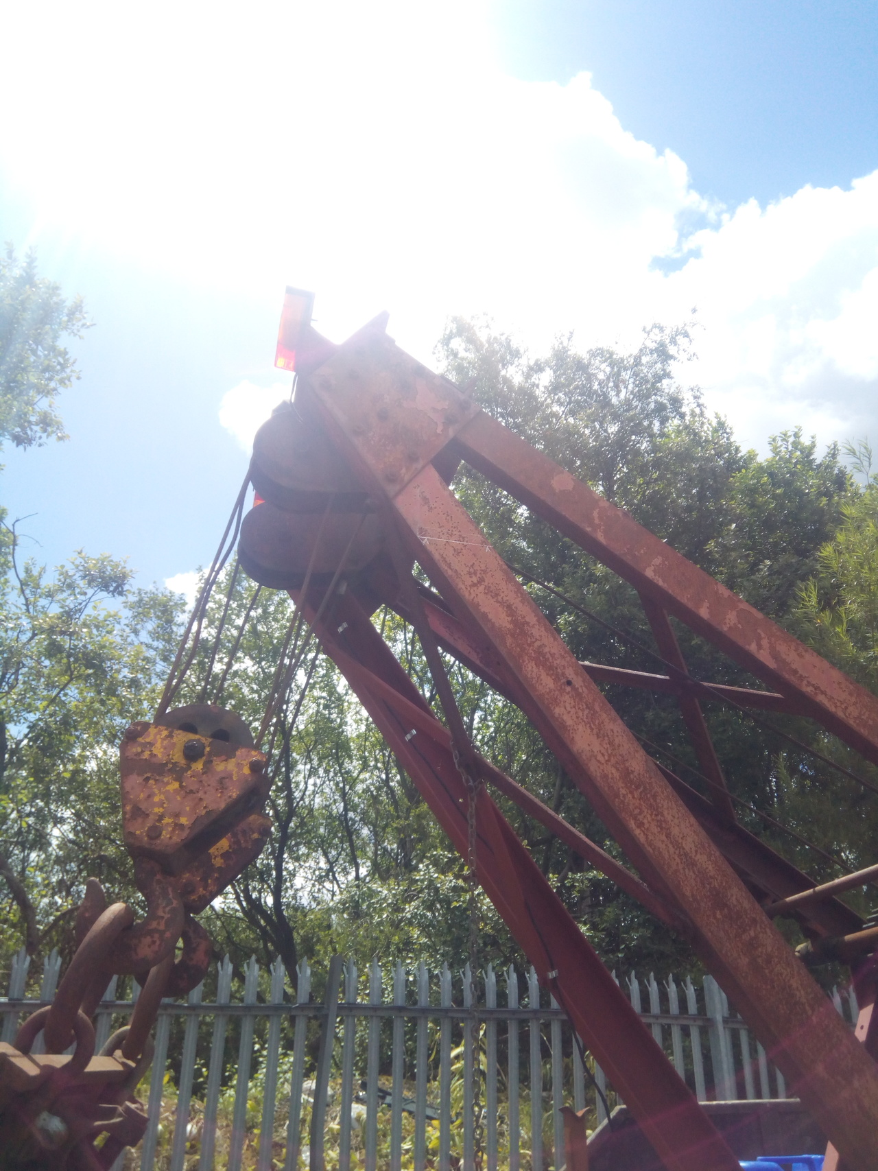
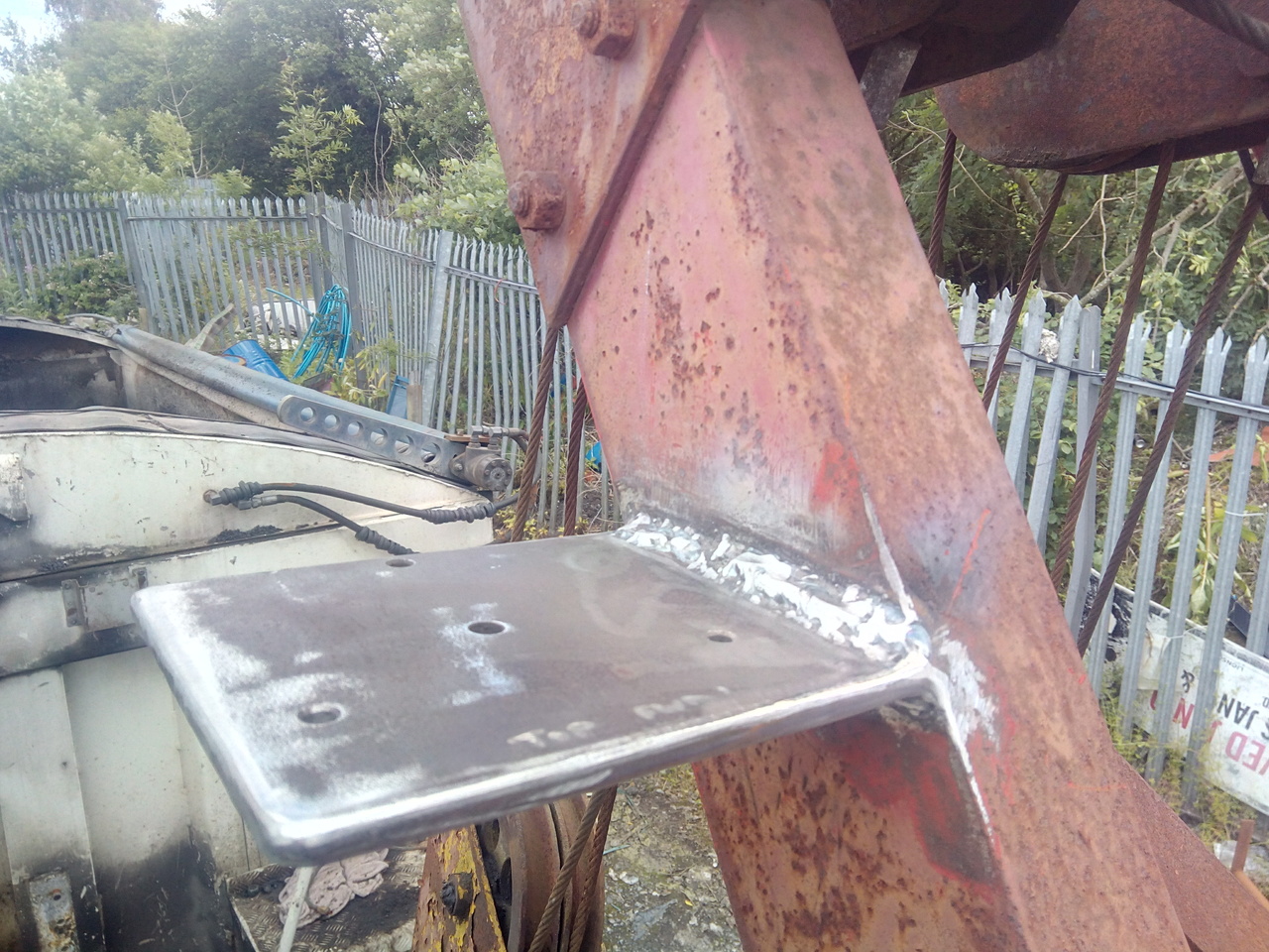
(The Überbräcket is so named because it's only holding up a twirly light the same as the one on the roof, yet I made it out of a piece of 10mm steel that I had laying around that was the right size, and severely welded it. It's not bloody coming off without taking the crane with it, I think!)
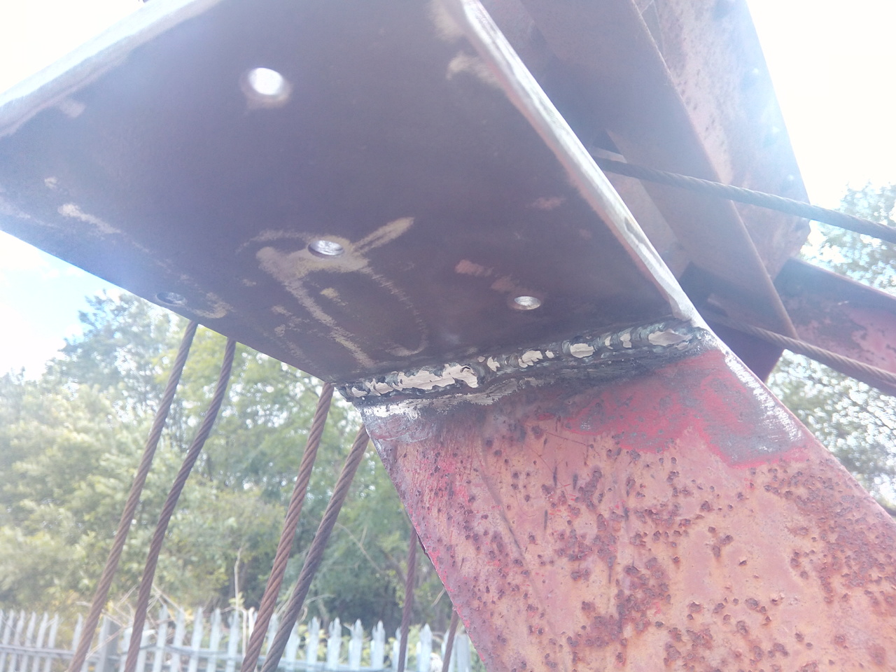
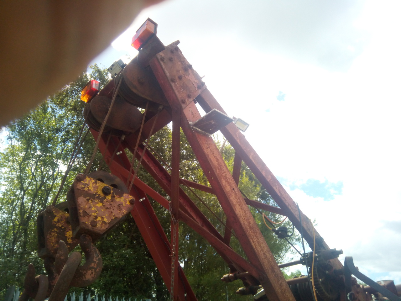
Not much more for it but to put the beacon on!
Yeah, sorta like that.
I also puttered about with a modern truck wheel that was laying about. Which I knew wasn't going to fit, but I wanted to see how much it wouldn't fit by. Because measuring n thinking abuot it is all well and good, but actually seeing it not fit is quite helpful.
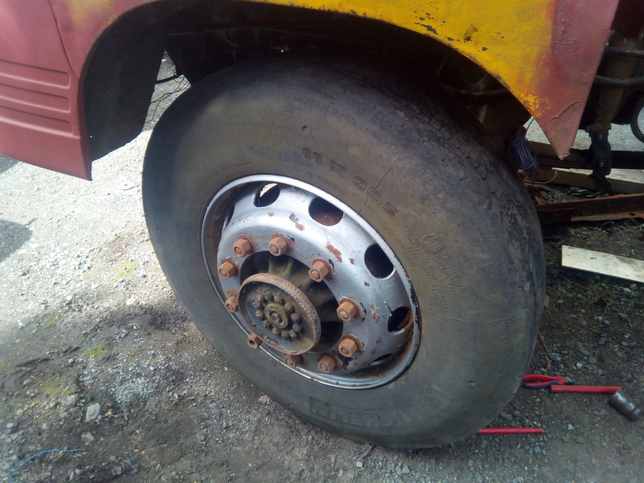
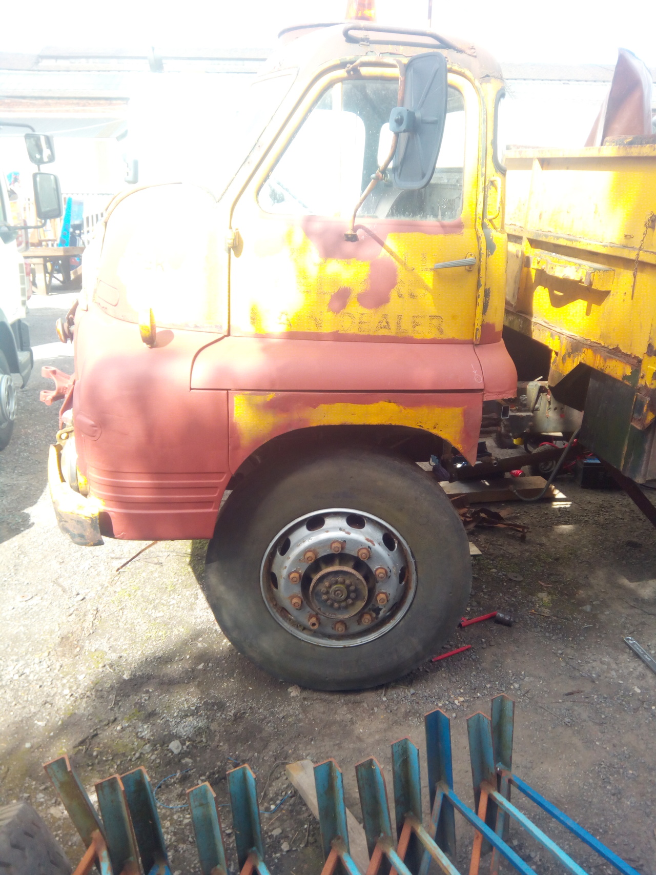
Tamber said: As good as it looks, there's some slight clearance issues. Some faffing about with measuring offsets, widths, etc. ensues. Currently trying to work out what I can get away with, wheel-wise, that lets me fit a fairly standard (modern) on/off M+S type tyre.
This 'test wheel' is a 22.5x7.50 and some brief searching tells me that the more normal modern truck wheel is a 22.5x8.25, so I'll try find one of those to check with. Oh, and the offset of the wheel I was testing with puts the inner lip of the wheel hard up against the track rod end, which is less than ideal.
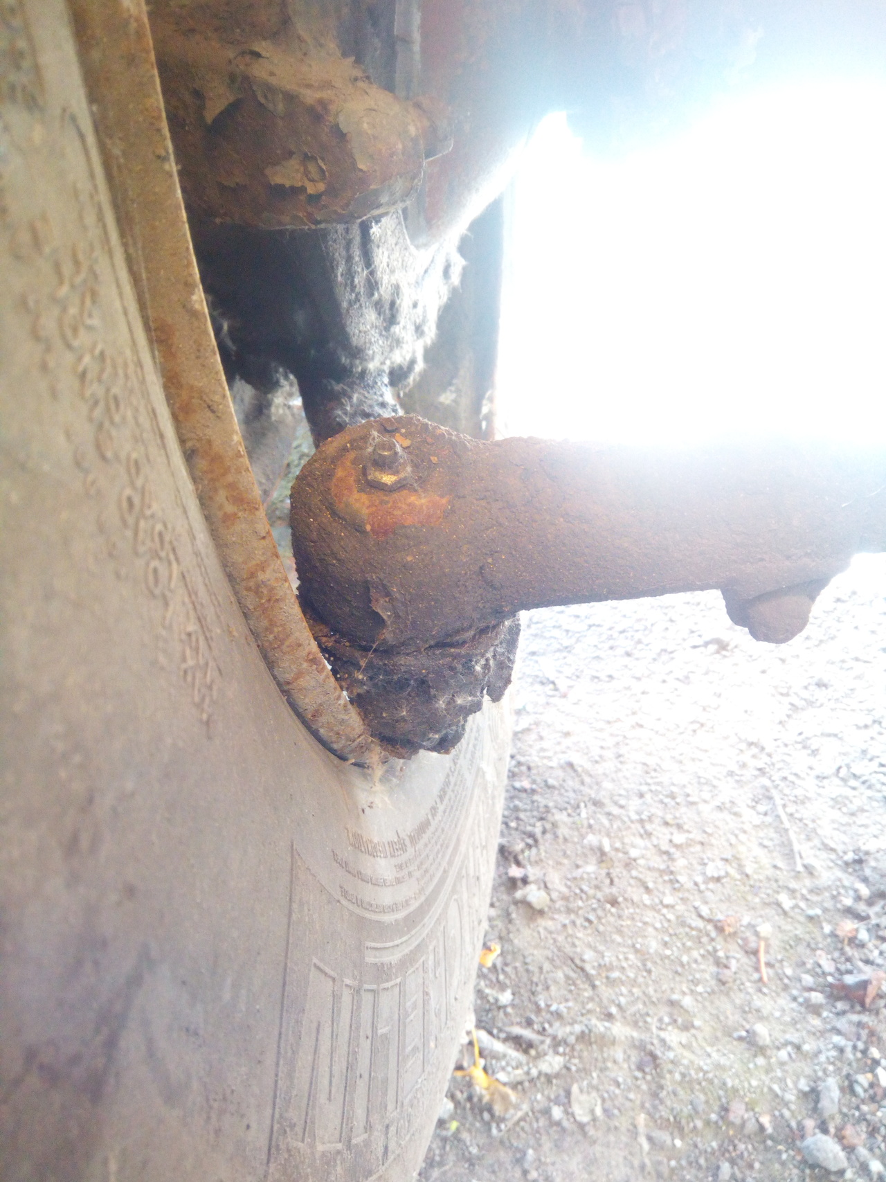
Might be a bit too much self-clearancing required there.
Early August 2018
Had an attack of the productivity. Booked the weekend (Sat, Sun; as opposed to my "weekend" at the time, which was Weds, Thurs) off and got stuck in.
A long way from perfect, but better!
Also managed to scrounge up some air-tanks from the scrap skip of a local haulage firm, who'd been buying wagons to cut them up for parts. Then dug in work's scrap skip for something that looked about the right length, and tada... an air-tank bracket, with some air-tanks. Edges of the bracket isolated from the tanks themselves by some air-hose cut lengthways (Which was also left over from a previous job!)
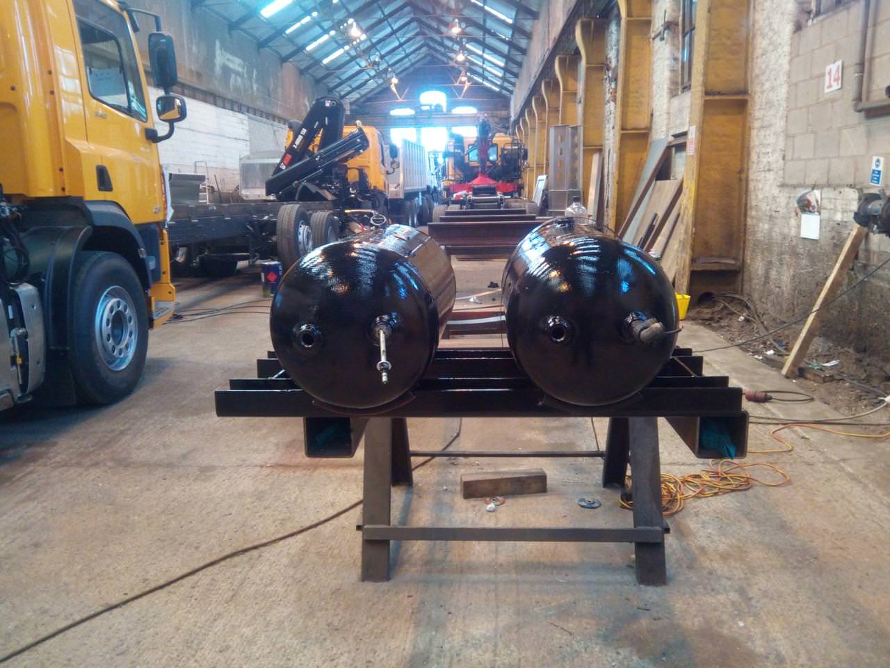
Drag the lot of it out to the truck...
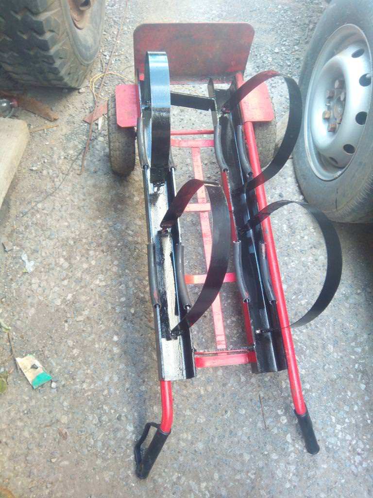
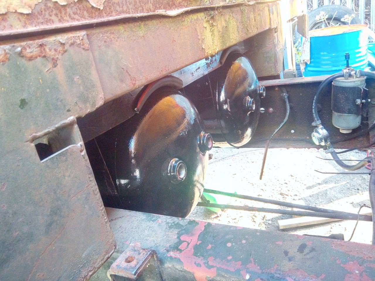
Where it fits in here:
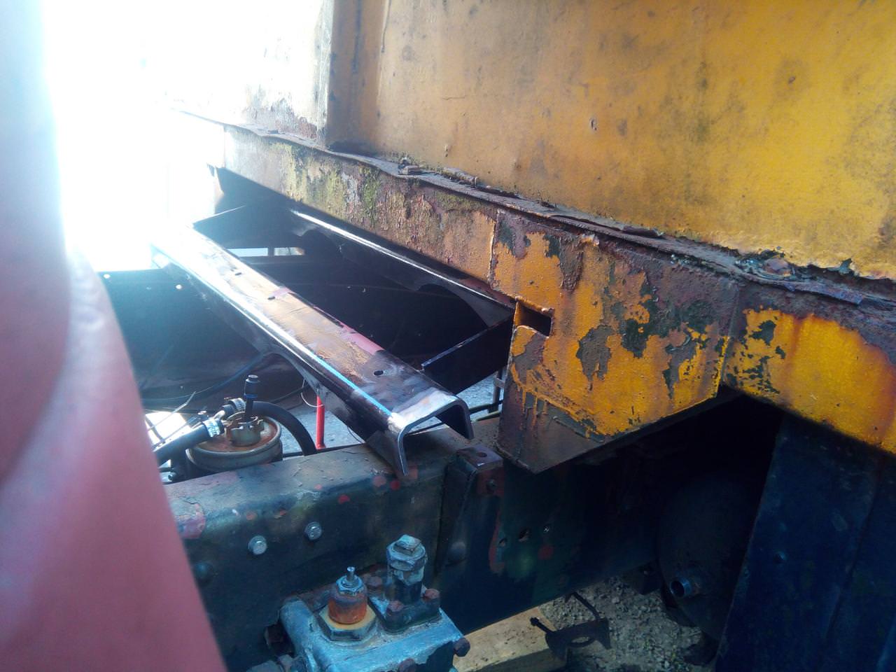
...I said, WHERE IT FITS IN HERE!
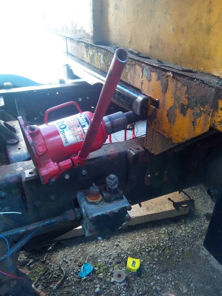
Snazzy! Now to get covered in shit, bash my head a lot, end up covered in not-quite-dried paint, remove linkages to gain access... and give them a bit of a tack ,because I was getting too fed up kneeling on gravel to weld them up properly. They're not coming out in a hurry, though.
Late August 2018
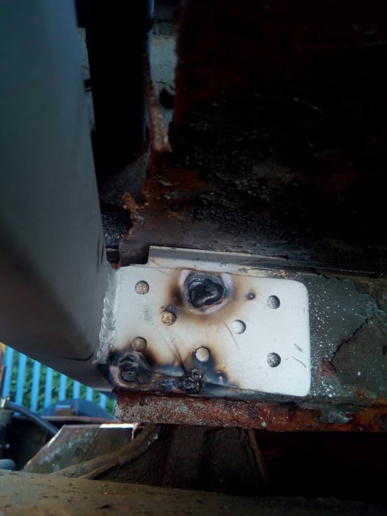
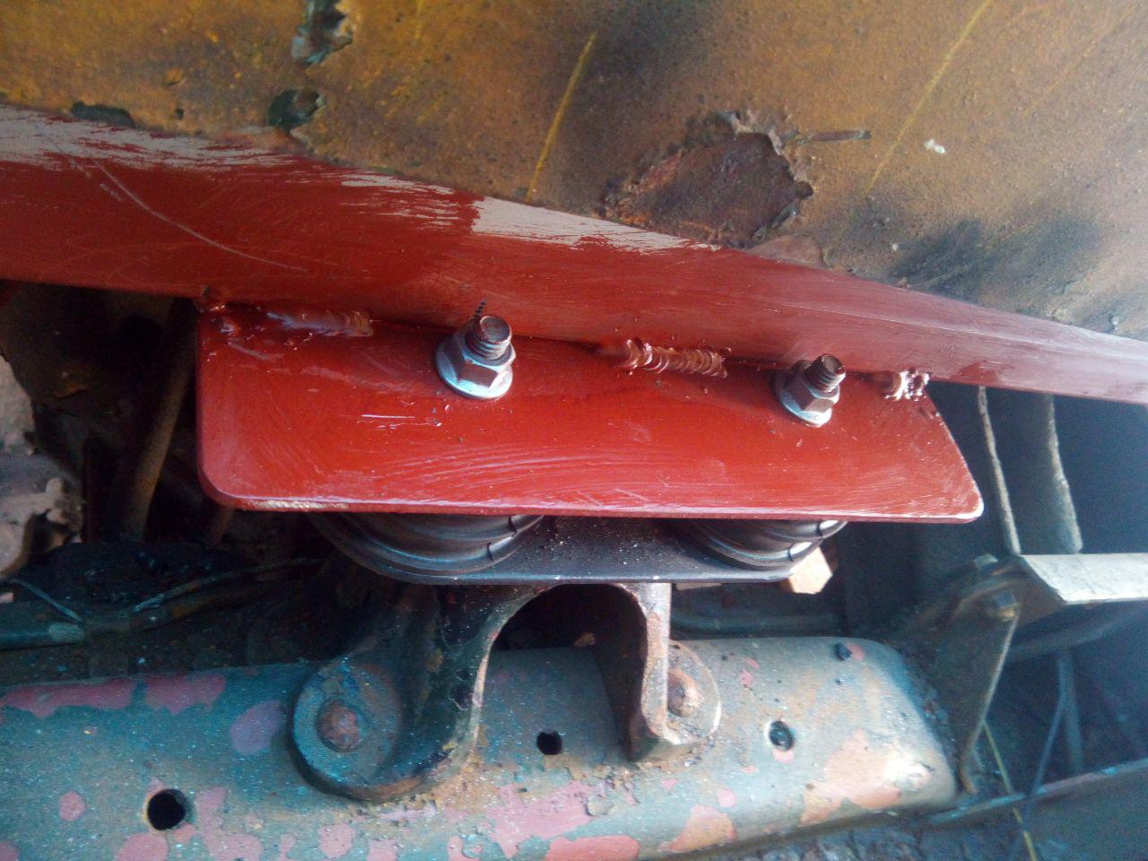
Cab mount time!
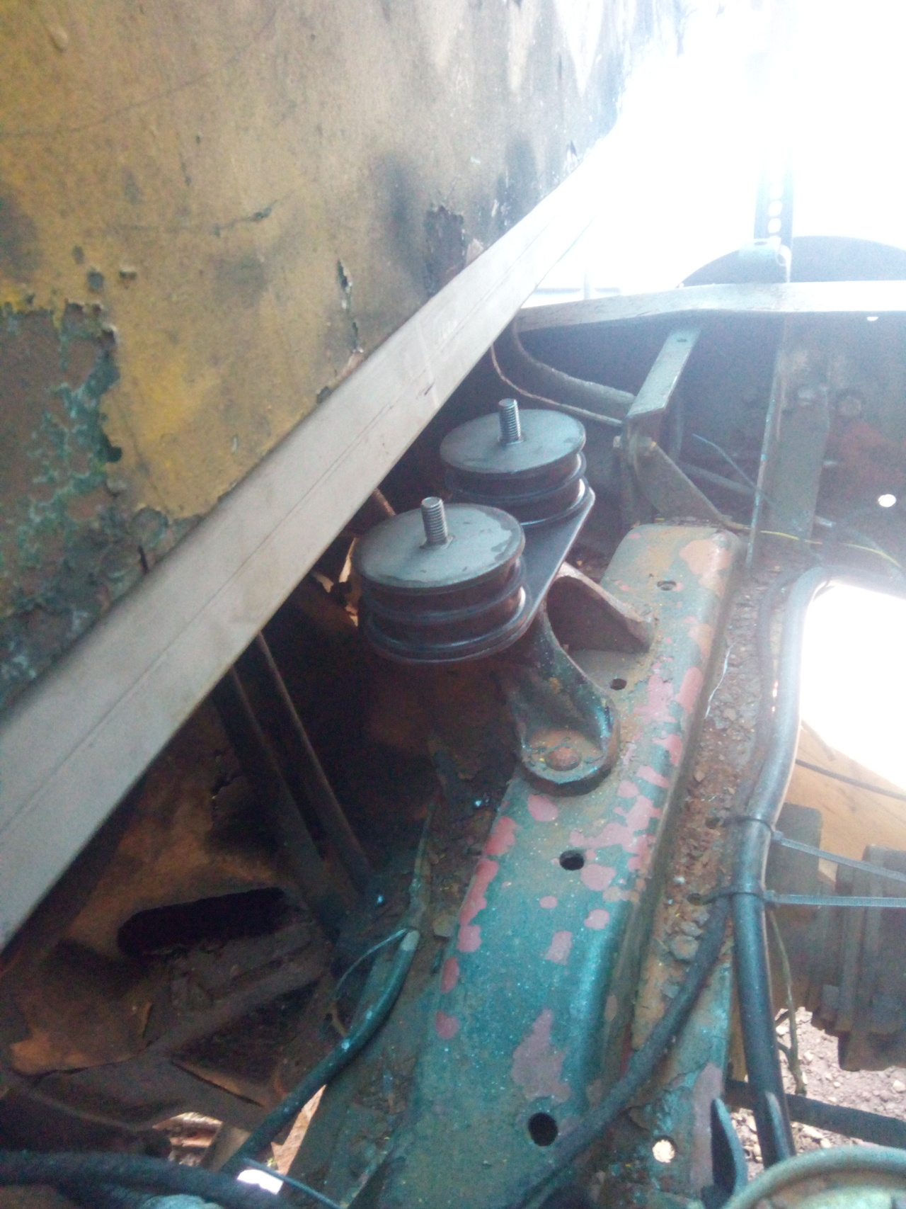
Just your bog-standard universal engine/gearbox mounts. I have another pair of them to go, one each, on either side of the front of the cab. But I want to get the rear of the cab made of metal again before I start surgery around the front mounts.
And then it turned out I can't measure things properly.
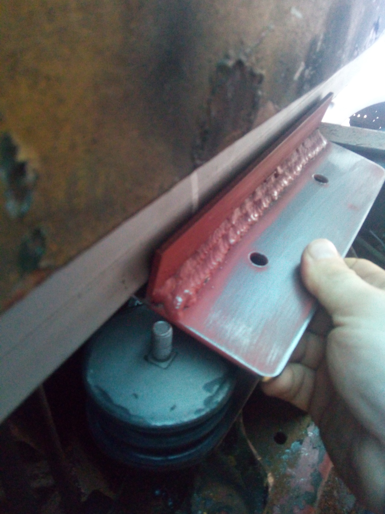
Those holes are meant to line up with the studs in the top of the mounts, and the upright flange was intended to then weld to the box section to spread the load a little bit. It does go on backwards just fine, though, so I'll do some trimming -- remove that upright -- and go from there.
A Few Days Later
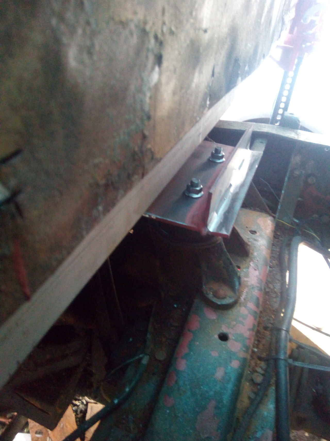
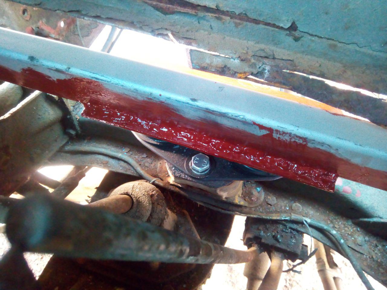
Only stitch welded on this side, because I needed to leave room for the nuts to go on. (And it was tight even as it was; the flange on the nut was pressed up against the box section.) If I were smarter and thought things out better, I would have started that leftmost one from where the tack was, so it'd consume it rather than leaving an ugly glob. Something for me to remember next time, I suppose.
Hide the ugliness with paint, I guess.
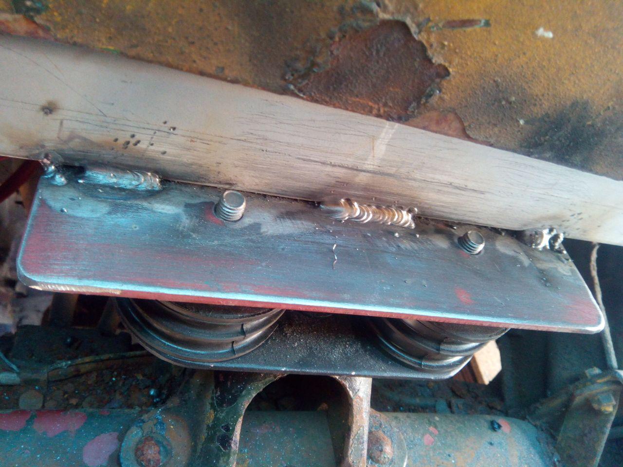
Inner edge was fully welded, despite great personal discomfort, because... uh... reasons. To weld this, I was curled up like a cat, around the front of the passenger seat and half-draped over the engine cover. Really, fully welding it is overkill; the attachment of the bracket only really needs to be as strong as the bolts holding it to the rubber mount. Or, honestly, slightly stronger than the rubber of the mount.
Mid-September 2018
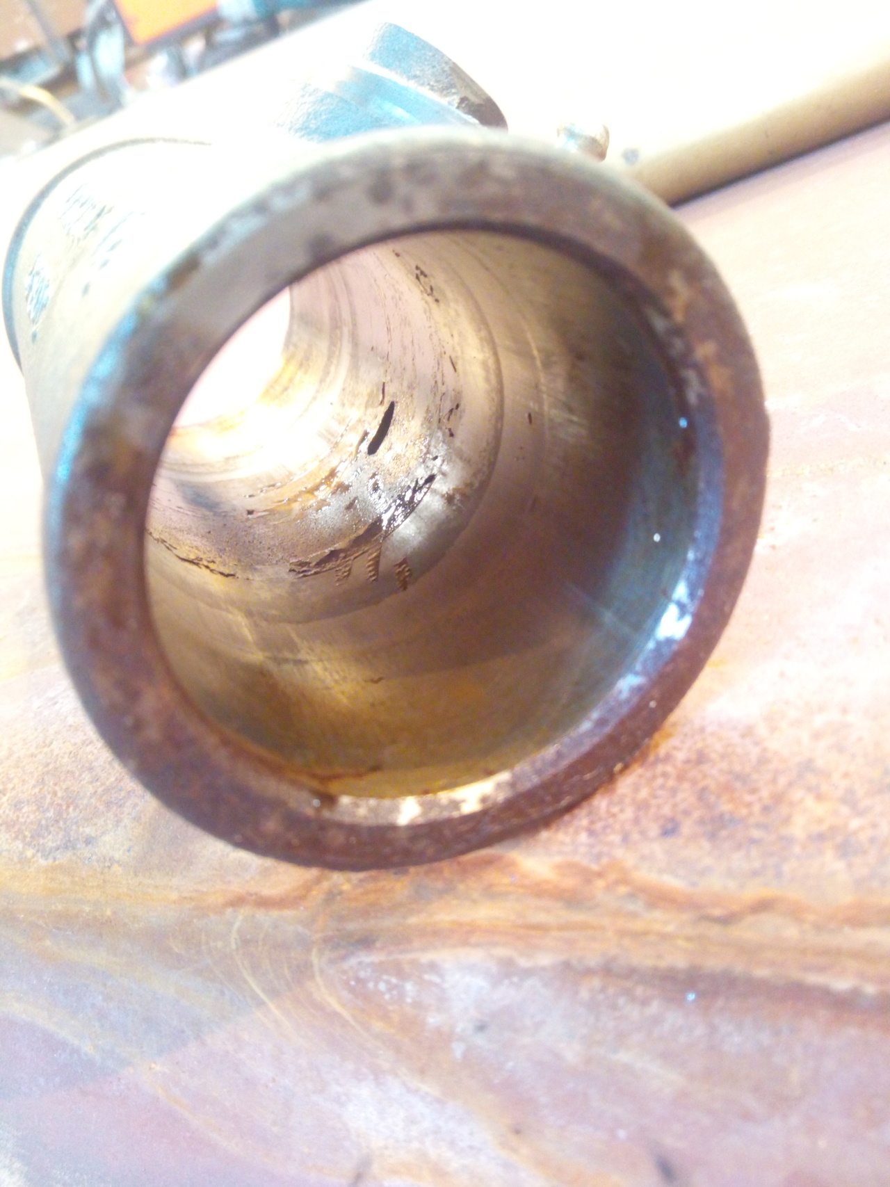
Went to go change the oir in the air-compressor. Couldn't find the filler/dipstick. Hmm.
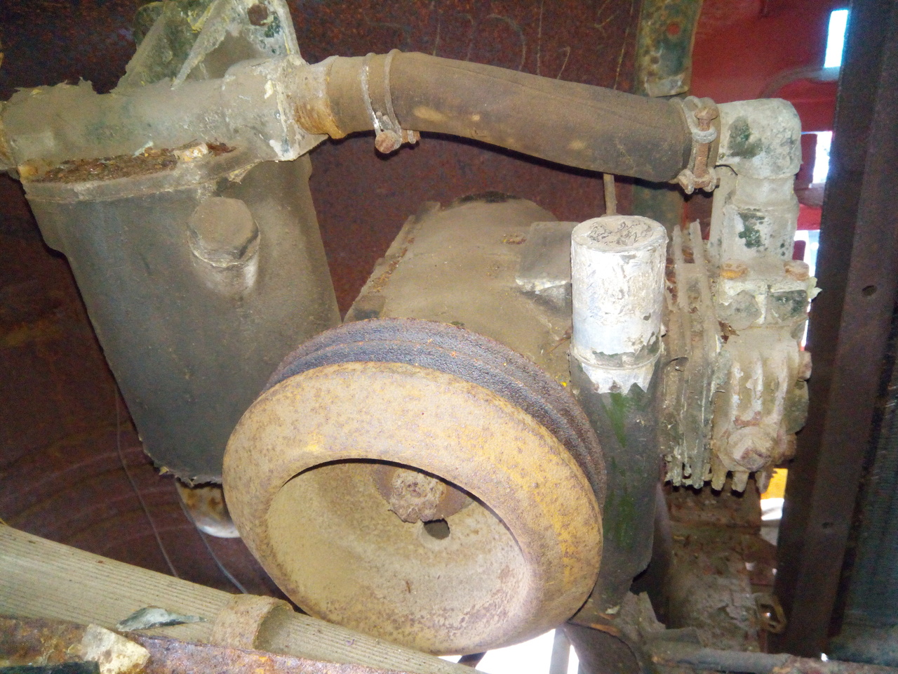
That's a bit shit, because it should be a knobby knob thing, like:
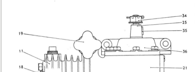
Seems like it met an unfortunate end.
And, on the note of unfortunate ends, the whole truck very nearly met one in early September. I hooked up the battery as normal so that I could tinker some with the wiring (and make another attempt at getting the engine to fire, just to see if it's possible to limp it to the workshop & back.), I'd just gotten into the driver's seat and had my hand on the key when the oil pressure warning light started to glow dimly, getting brighter and brighter.
"Well, that's weird", thinks I, then I start to hear crackling and the cab fills up with smoke. The cab is covered with a tarpaulin, so I'm at this point inside a big plastic bag with the smoke from burning wiring being blown in from the open passenger's door.
It's amazing just how long it feels like it takes to undo a battery terminal while the truck's trying to set itself on fire! Anyway, it turns out that the flexible metal conduit from around the battery positive cable had scooted up at some point until it was just barely touching the ring terminal and it was grounding out on the chassis. It wasn't making a good enough contact to cause noticeable sparks when I connected the negative lead to the battery, but enough that the conduit got pretty hot!
Once it cooled down enough to touch, I pulled it out and the battery cable inside the conduit was looking pretty ugly.
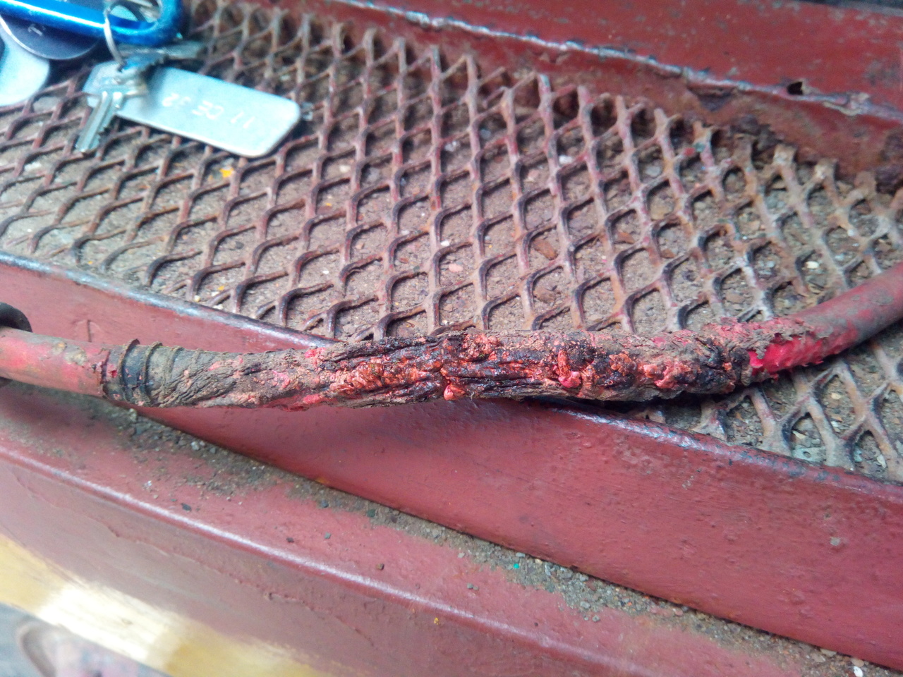
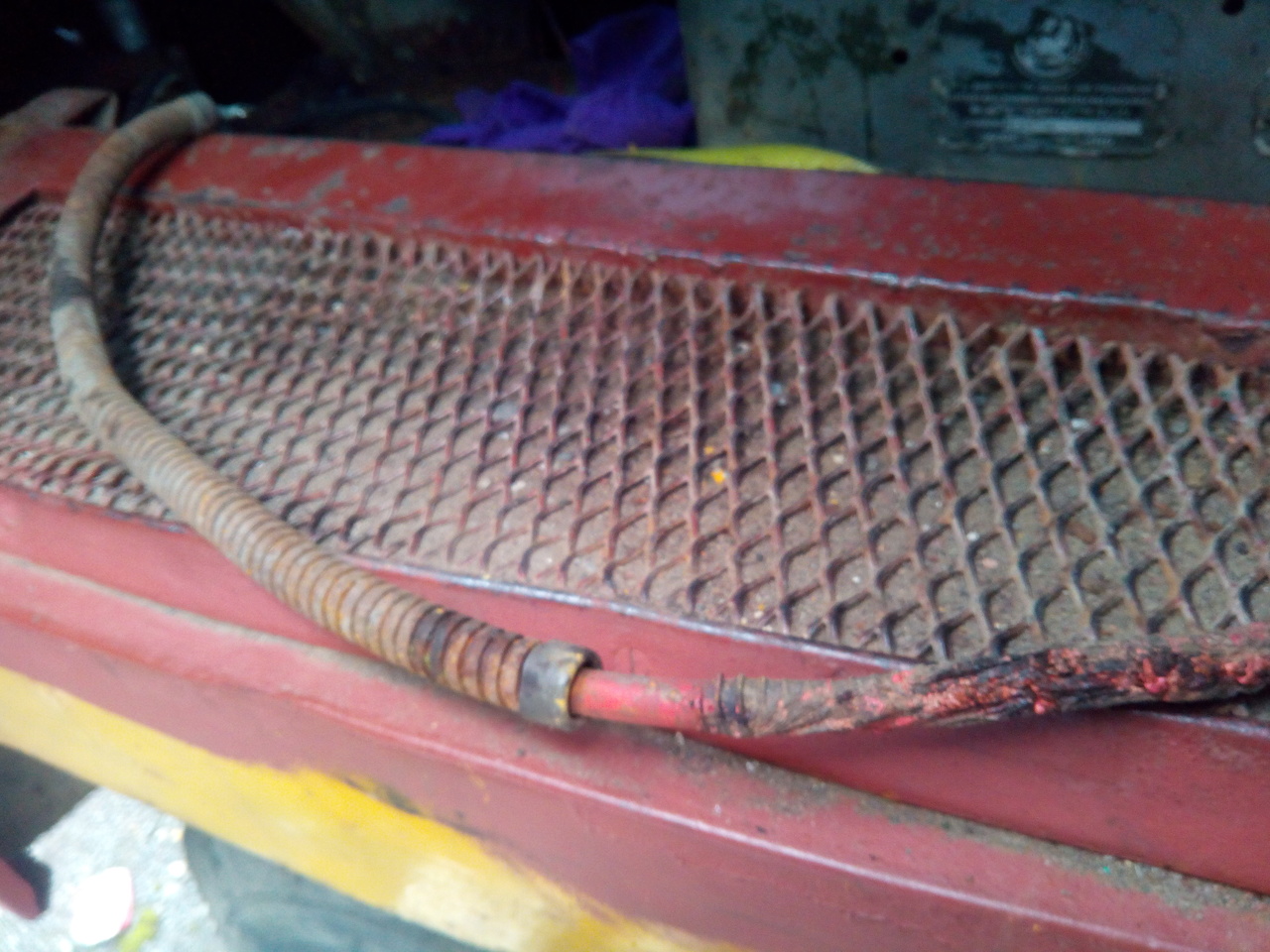
Got pretty lucky there. Had to replace a length of battery cable, and repair a bunhc of wiring that passes through the same area.
Also got my new old-stock front wheel cylinders in, and pulled them apart to check the seals!
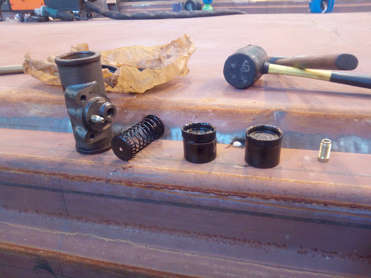
Found a hitchhiker!
That's probably not seen the light of day in over 30 years!
Anyway, the seals all looked and felt fantastic, and the bores were in great condition too, once the thick greasy storage protectant was washed out of them!
So, looks like I'll be using those, then! (Spoiler: I did. Nothing has gone catastrophically wrong with them yet. Though, to be fair, I've not fully bled them out yet, so they've not really seen full pressure.)
Late September 2018
Remember that air-compressor I couldn't find the filler on?
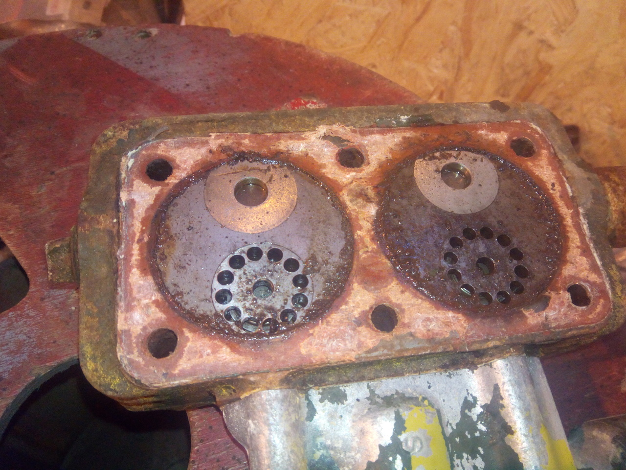
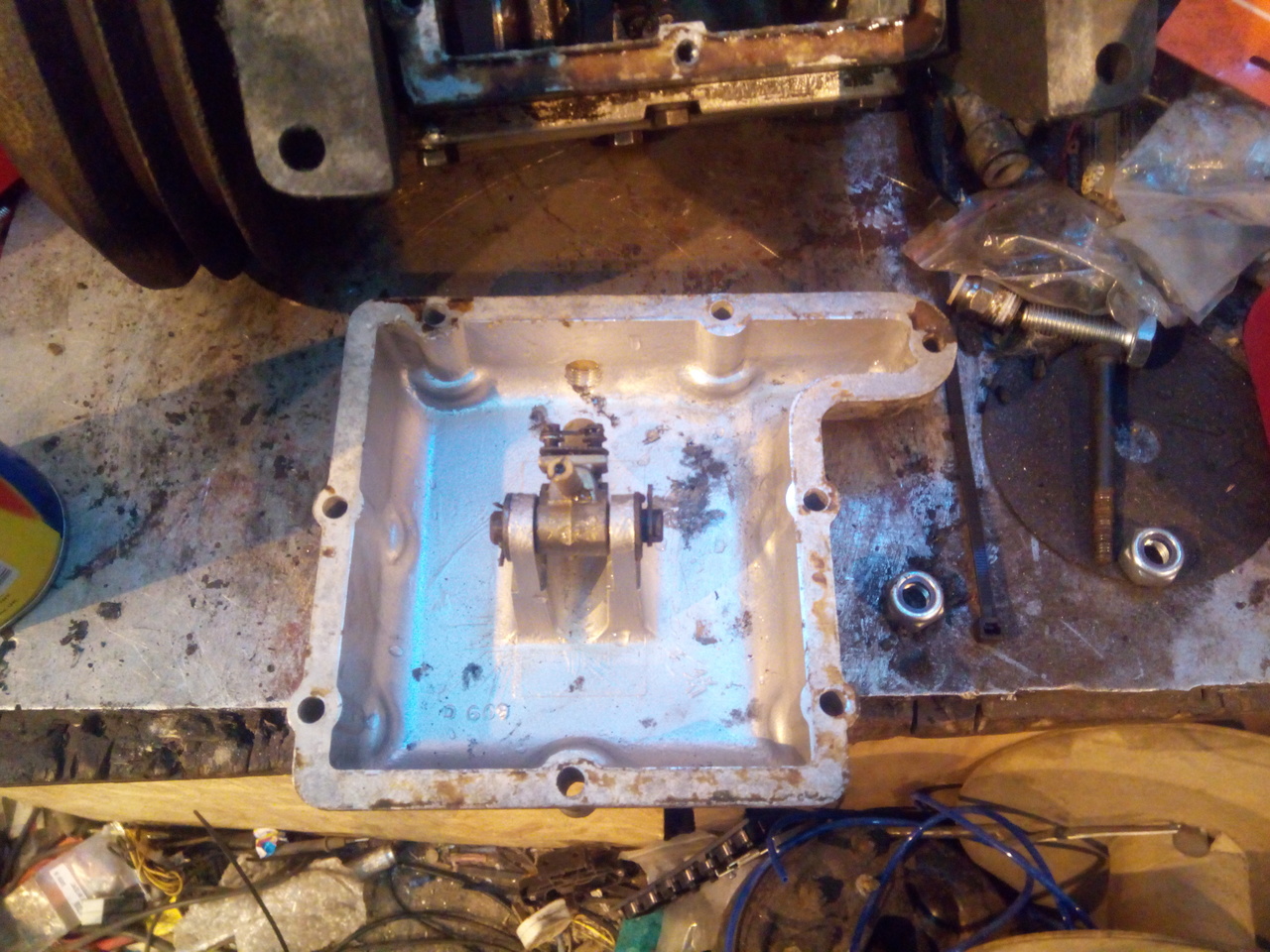
Not pretty, but cleaned up pretty easily and there's no scoring in the bores. The check-valves all seem to work quite nicely, and I cleaned out the passageways as best as I could. One of the bolts holding the inlet manifold down has a pretty gacked thread, so I've got a tap on order to chase the threads in the head just to make sure, and I'll get some new bolts on order. (1/4" UNF, so nothing particularly exotic.)
I also had to break up the remains of the filler cap, since it seemed to have bonded itself into the threads and was stubbornly refusing to rotate. (I'd drilled two holes through it so that I could use circlip pliers to try unwind it. It bent the circlip pliers, then the edges of the holes started to break up.) Very careful -- almost surgical -- chipping with a thin chisel, and picks...
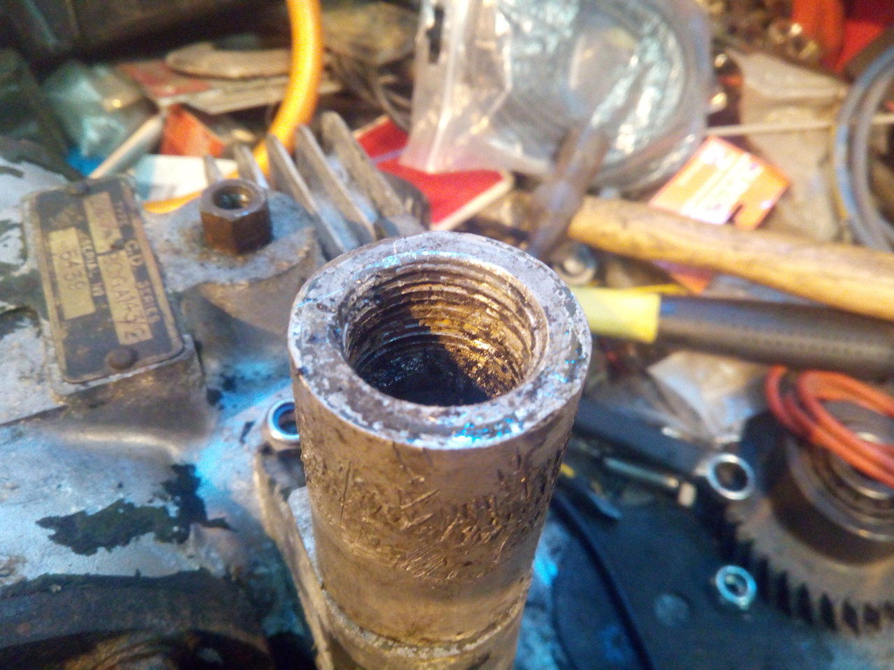
Saved the dipstick, though!
Not too shabby!
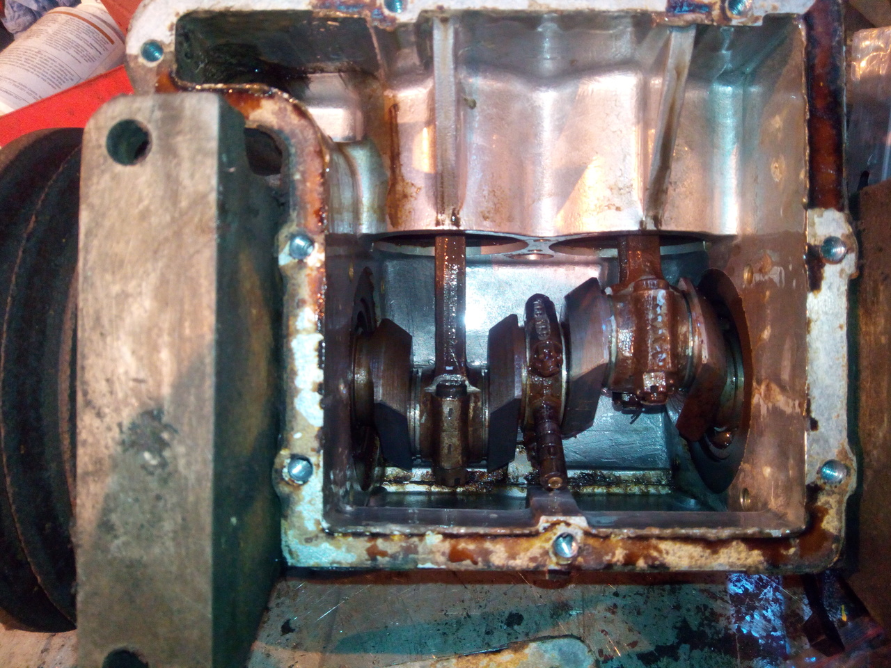
Now, the sump... Brace yourselves, it's not pretty...
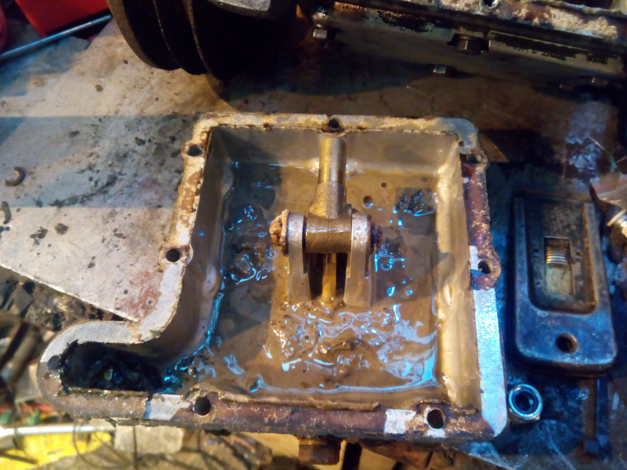
Sludge vs. Industrial Jetwash
Jetwash wins!
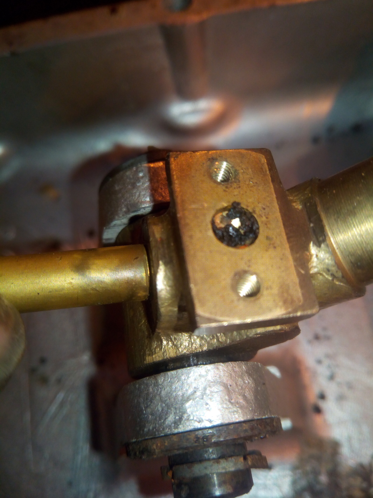
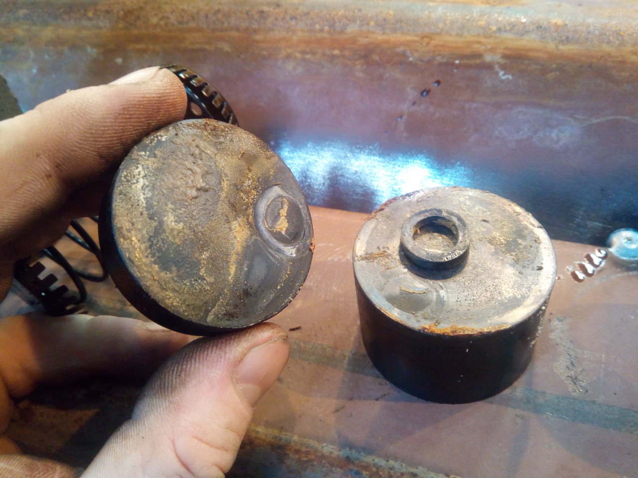
Concerningly, the little relief valve on the oil pump looked like it was stuck open. It's also picked up a few fragments of the plastic filler knob after my previous precision removal process, but it was already showing signs of problems even before then. The back-side of the other part to this relief valve had a much older-looking deposit built up on it, and it was wedged open.
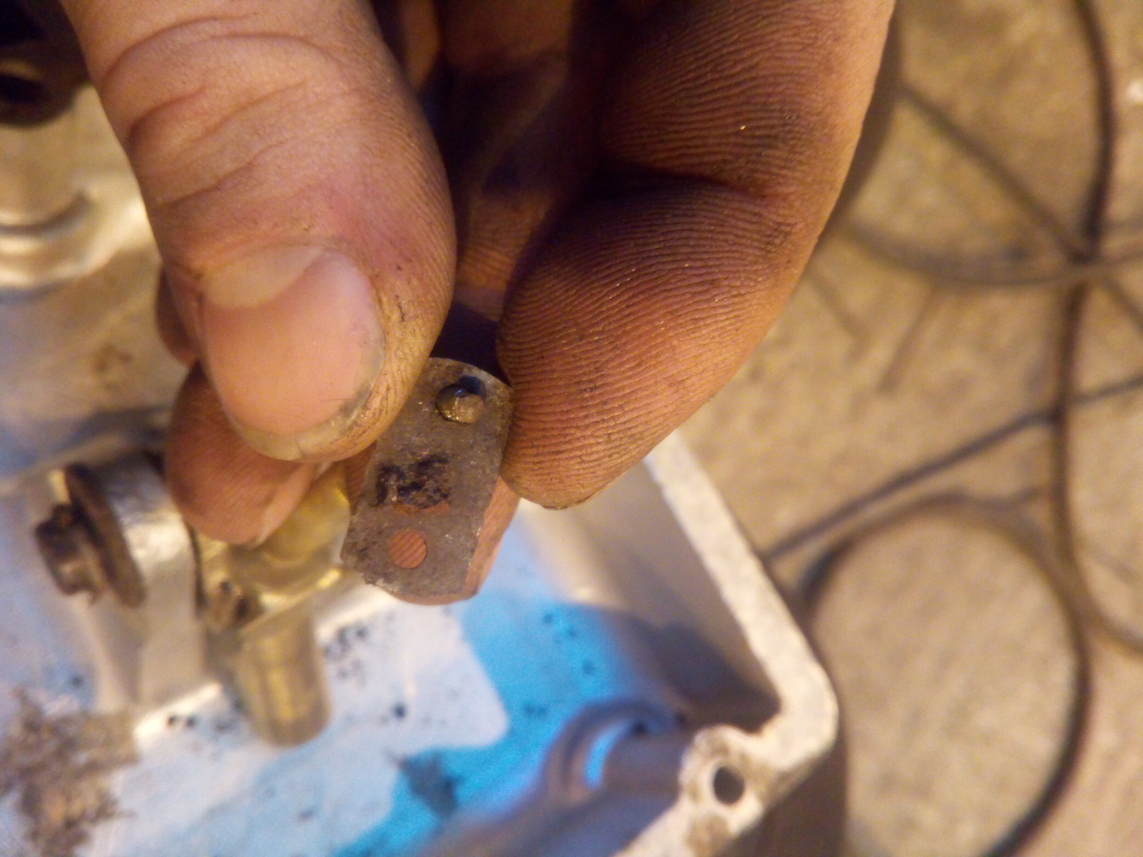
It's a pretty clever little mechanism, this oil pump. The shaft of the eccentric is the pump piston, and it's hollow -- with a little brass orifice in the end -- so that the pressurised oil squirts up it and is forced into the crankshaft; the pressure relief is a flat plate over a drilling, held down by two little screws with springs, such that once the pressure reaches its limit, it lifts the plate and squirts out. Nice piece of design and engineering.
Mm, that's not altogether too pretty.
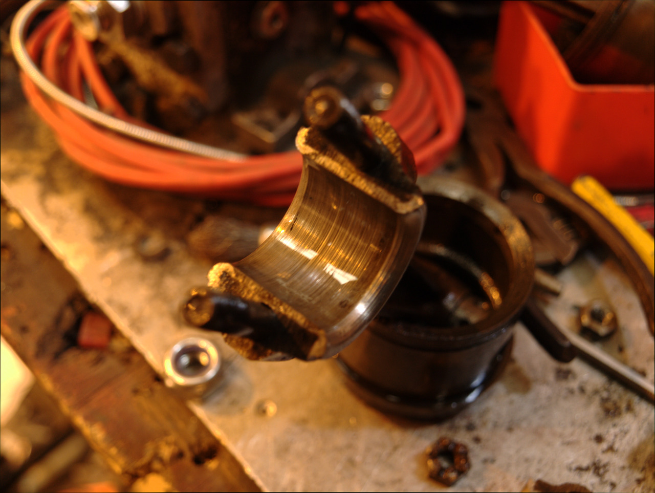
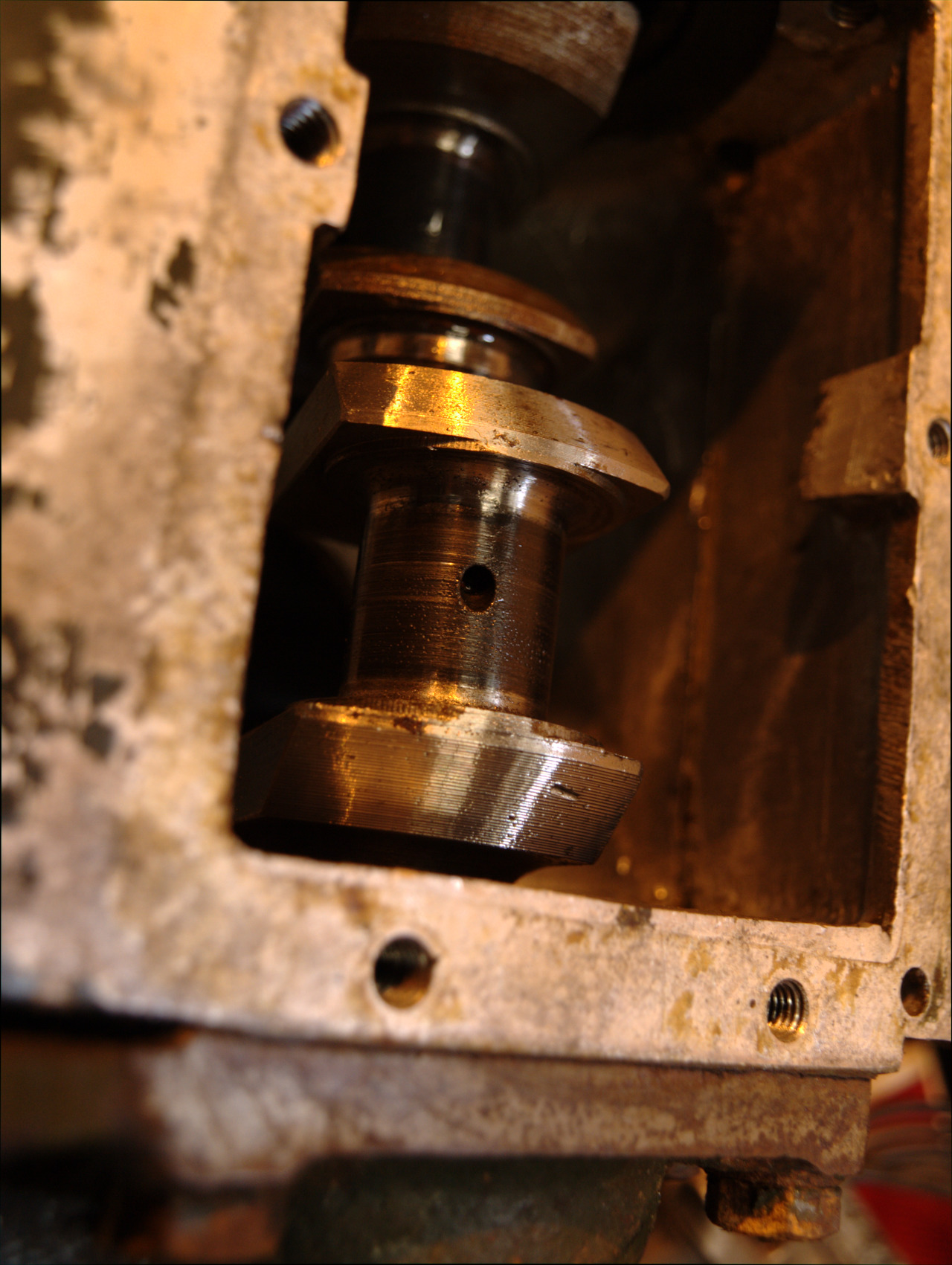
Nor is that.
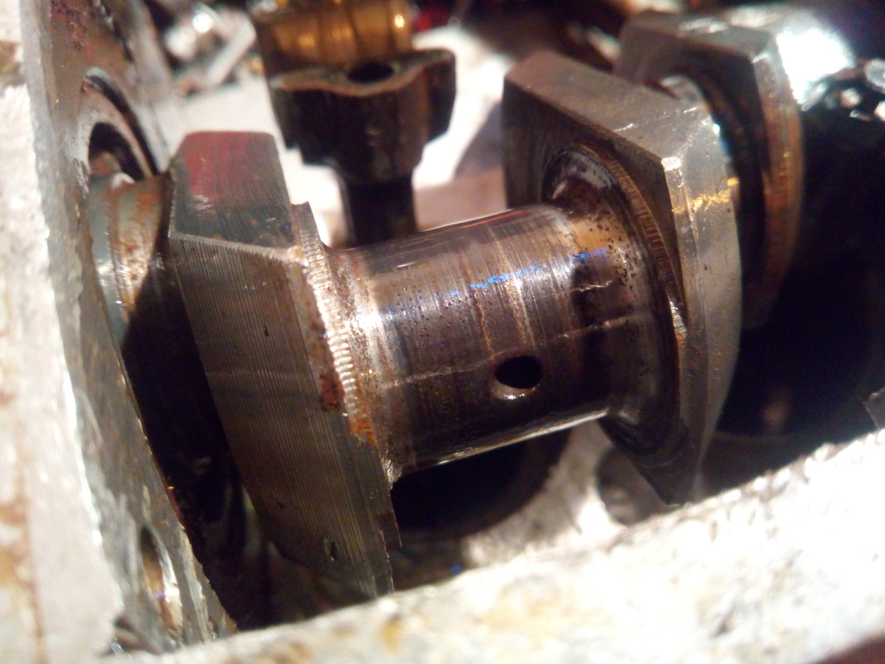
I also cracked open the Drawer of Excessive Precision (Above the Drawer of Insufficient Precision, which houses all my hammers and other tools of "Fit, damn you") for my micrometers and did a quick bit of measuring. The rod journals seem to be within the realm of cleaning up sufficiently with a bit of polishing; the big end bearings having taken the brunt of the damage as expected, being white metal.
The machinists precision G-clamps gave me some numbers (I'm majority metric, so bear with me! 😁) :
№1 rod journal: 22.22mm, №1 big end (vertical, i.e. in line with the rod): 22.5mm. Clearance of 0.28mm, or ~11thou.
№2 rod journal: 22.3mm, №2 big end: 22.45mm. Clearance of ~0.15mm, or a midges under 6thou.
Big ends are just a touch out of spec. :) I'll see what the crankshaft mics out to after I've polished the journals, I can live with it being a hair undersized so long as I can get the rods to match it. I still need to finish tearing the compressor down fully, measuring the bores and whatnot, but so far it looks otherwise to be pretty good. I'll just keep on keeping on, for now.
My current thought on the matter is: Fuck it, it's out of spec but might not give me problems. We'll run it and see.
Mid-October 2018
I still need to tweak the bracket for the indicator switch, because it doesn't fit where I first planned it, but that's not the end of the world. All the wiring will be tidied up when it's closer to being completed.
The compressor's been broken down a bit further, and I've got a bearing separator on order so that I can pull the ball-bearings off the compressor crankshaft. The ball-bearings seemed okay at first, but I've noticed that one of the front ones was beginning to feel (and sound) a bit crunchy, so I'm going to replace all three.
Somewhere, I have a notebook with all the measurements I've made. The bores are both in great shape, not tapered or ovalled; and... I'll have to go dig the notebook up to run through the numbers for the crankshaft, but the rods certainly don't feel loose on the crank after giving the crank journals a gentle polishing.
I've also run through the various threads that needed cleaning up (Mostly 1/4UNF; the thread on the nose of the crank is 1/2" UNC, and I'll need to get a new castle nut for that, but I don't see that causing much bother; and the thread for the filler is 3/4" BSP which is handy since I have hydraulic blanks spare in that size. :D )
Also: 1"-14 Whitworth is 3/4" BSP. But now I have both taps. Even though they're the same. Well, at least another strange Whitworth tap in my toolbox can be a conversation piece.
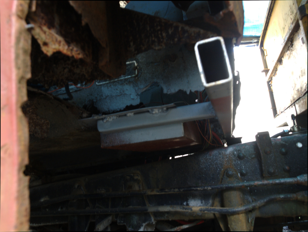
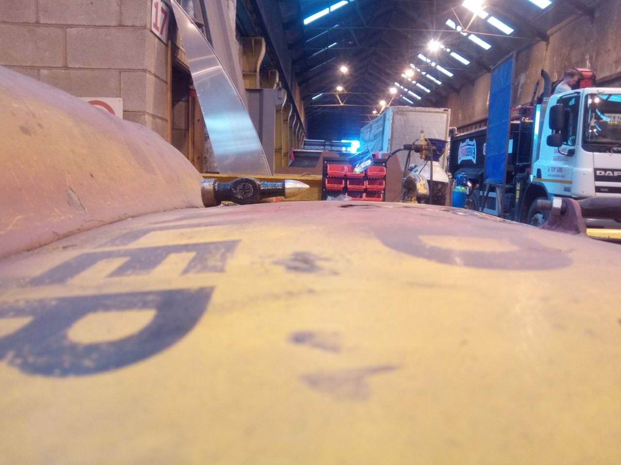
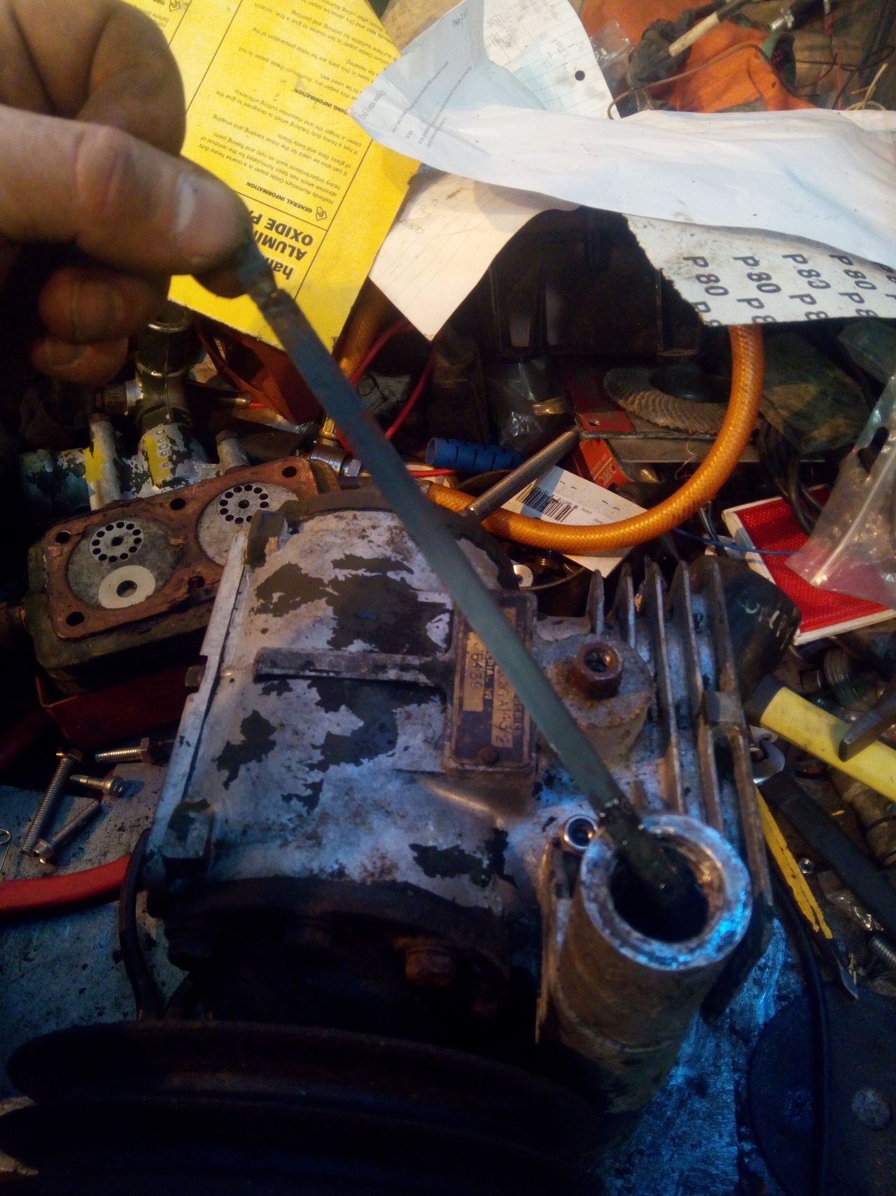
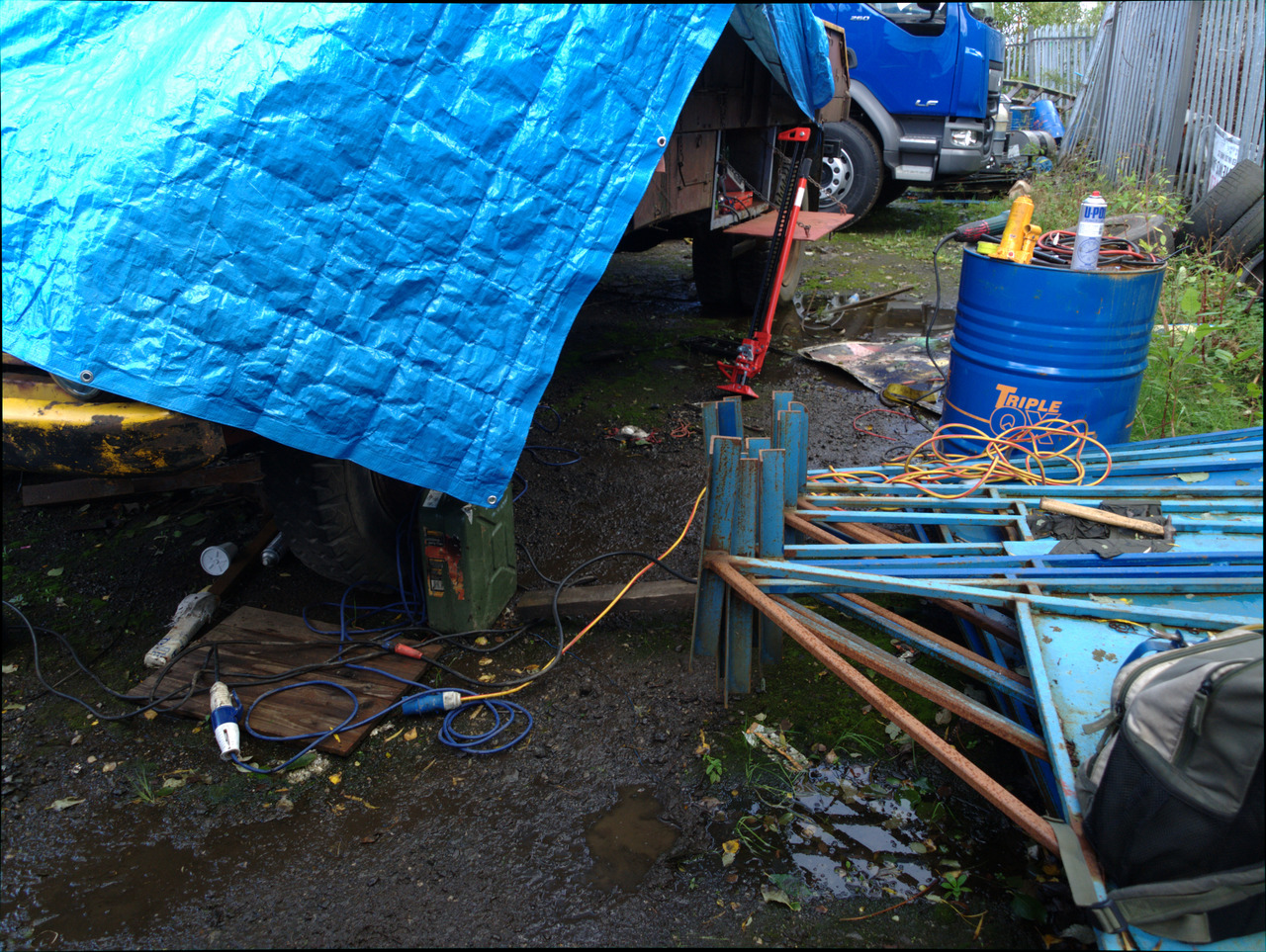
Just for context, a picture of the conditions I was working in by October:
Late November/Early December 2018
Some tinbashing happened. And wound up everyone in the workshop.
It started to get welded in, and bring the door back into shape.
...and then I quit my job.
Yup!
...well, I guess, I quit again, but for good this time.