16 Nov 2019
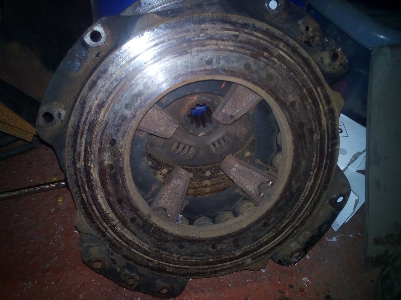
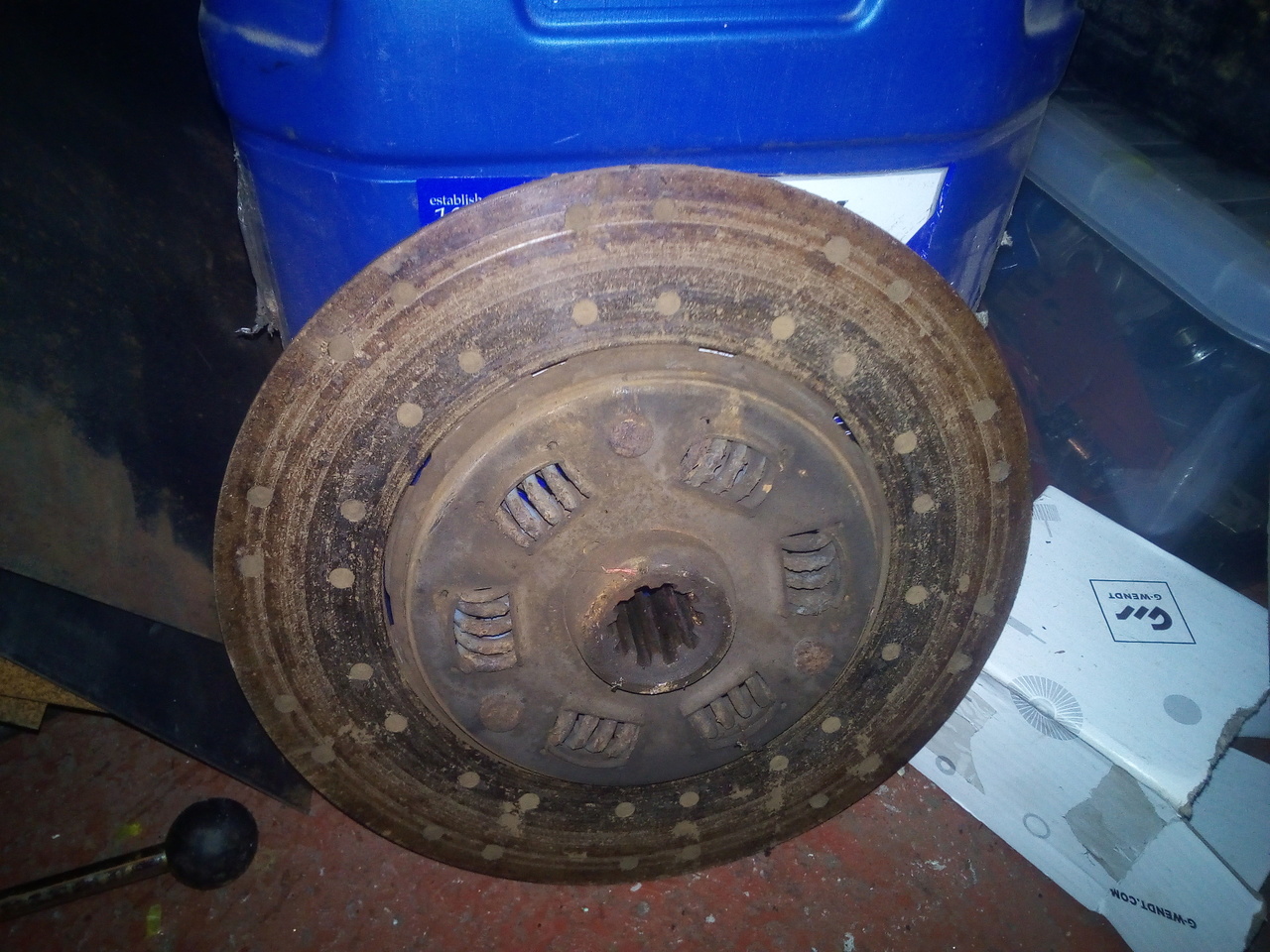
Freed the clutch, and I must say I've seen much worse drive into the workshop.
 x
x
And the flywheel:
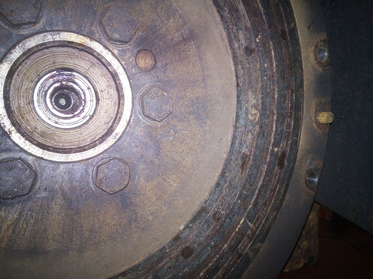
I'd like to note, just for reference, since I struggled for ages and didn't find directions in the WSM (Which means I'll find them, now, looking for something else): You have to take the flywheel out before you can take the clutch-housing off, because five of the seven bolts that hold it on, are behind the flywheel!
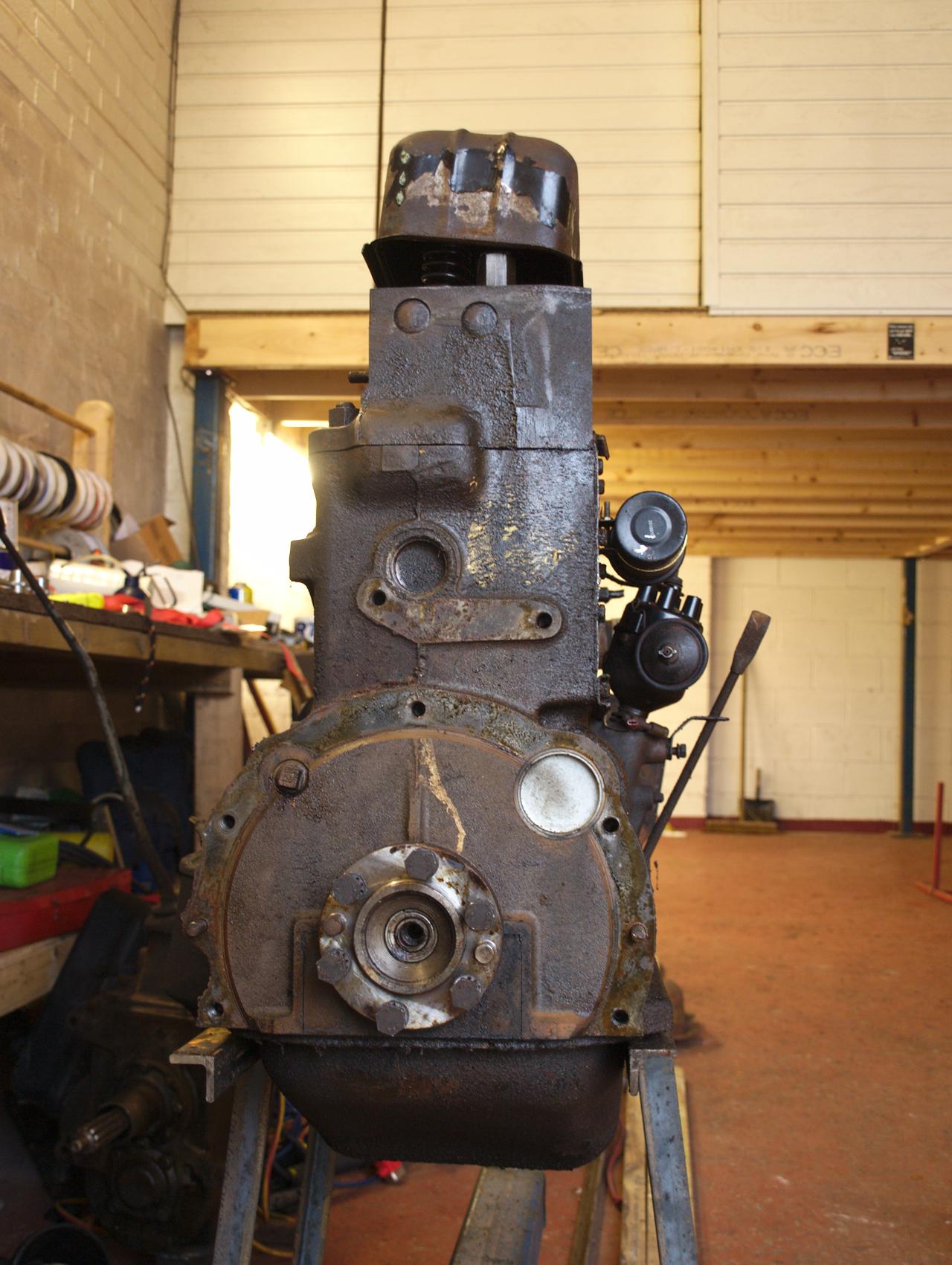
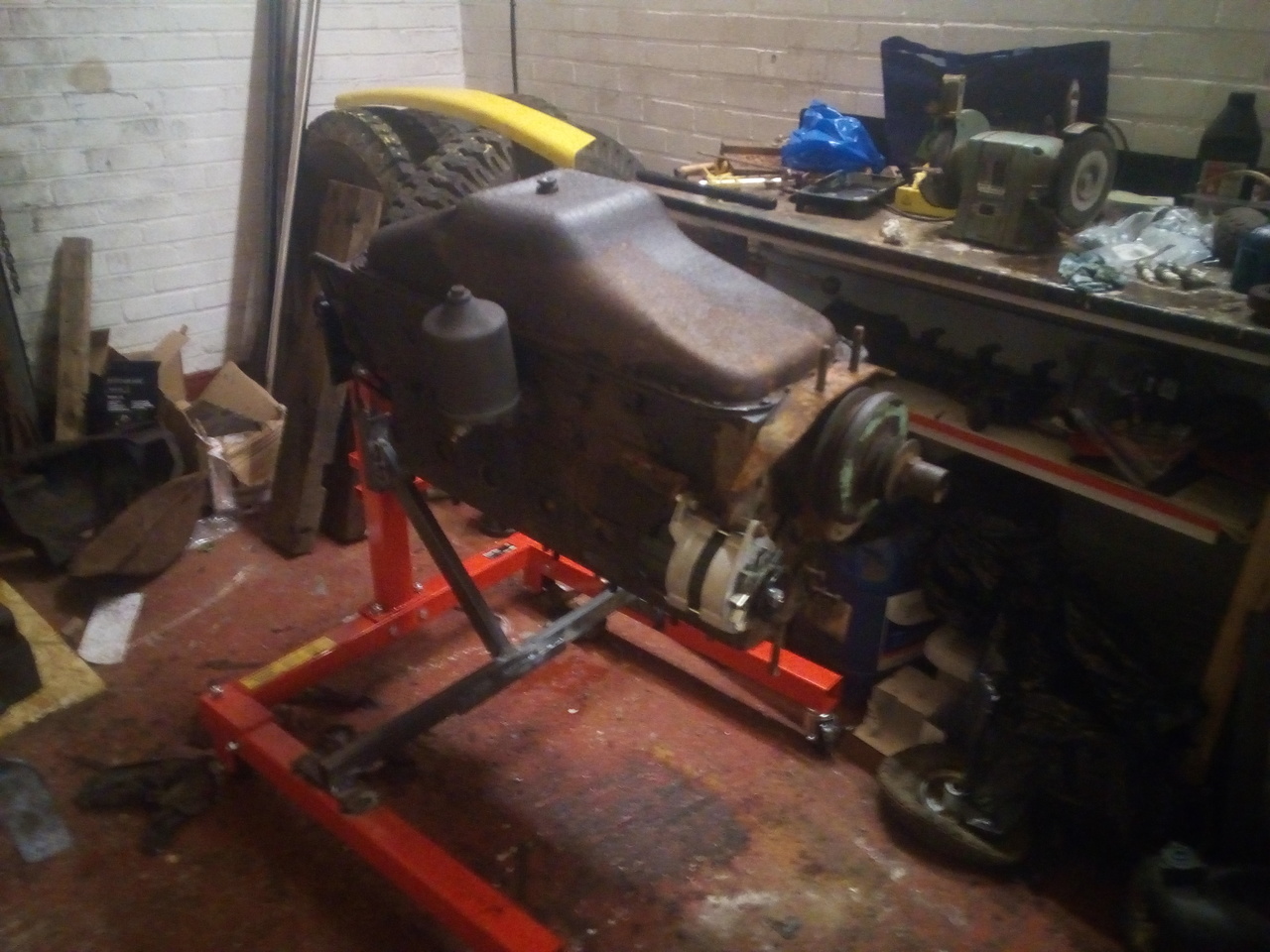
Anyway, with the housing off, I could finally bolt it to my new engine stand. Now, I expected it to struggle a little with the weight & bulk, despite being rated at 560kg SWL, but...


That was with the hydraulic part of the jack all the way down, and only the screw portion of it still holding the engine up.
Excessive droop detected! More bracing required!
I'm significantly more impressed at my "shoddy" little cradle, having seen that. To be fair, I didn't expect it to fare too well holding up the Bedford lump, but it's a lot easier to start from something rather than building a stand entirely from scratch.
The real trick is going to be bracing it up while making sure it's still disassemble-able, to save space. I have a plan, though.
17 Nov 2019
Housing:
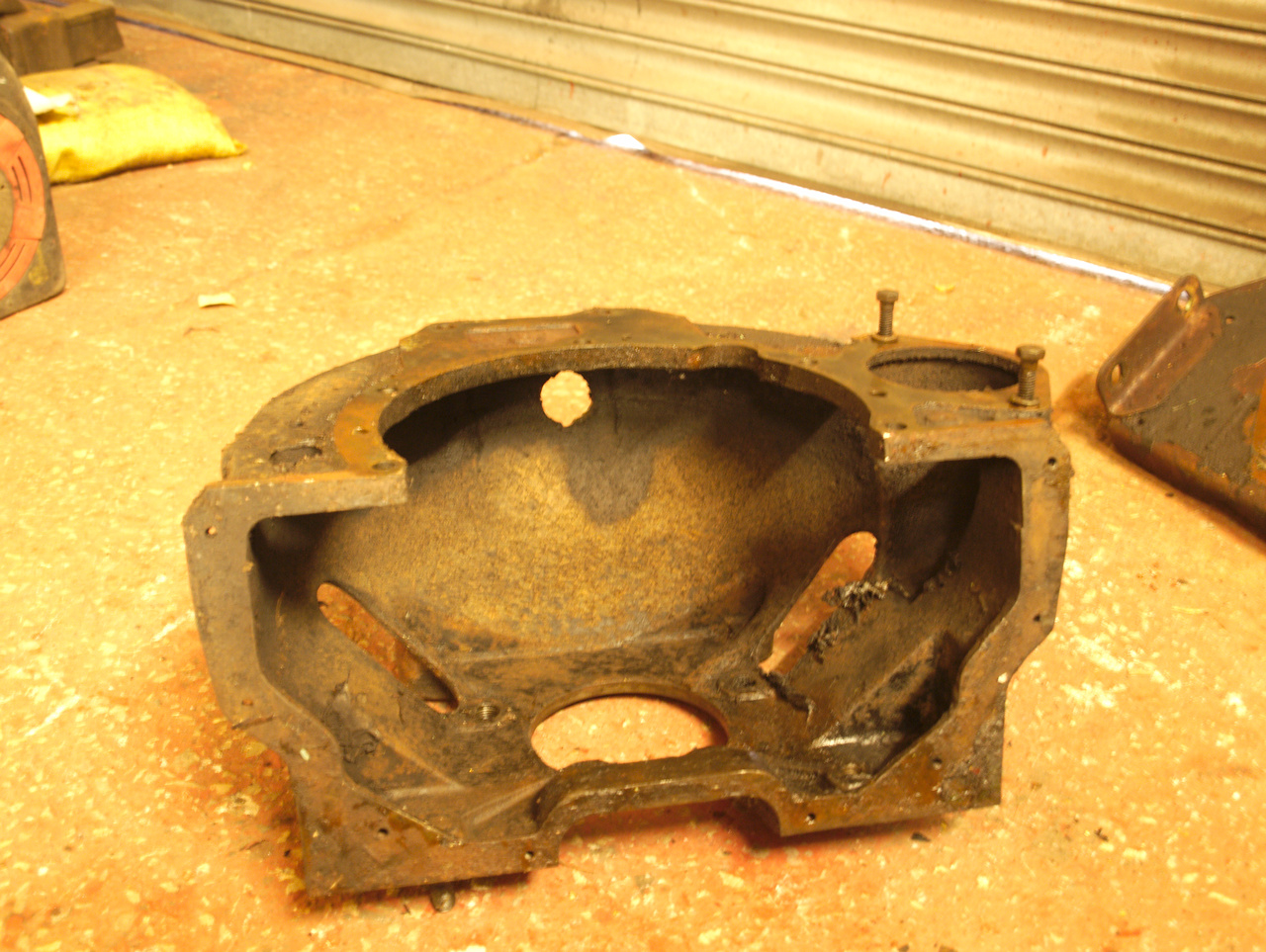
And with the tin bottom cover (ooh-er!):
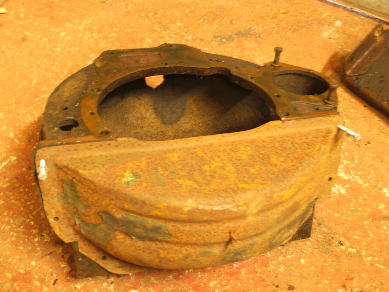
The little dangly rivet thing is factory. Presumably to prevent the drain-hole from becoming blocked-up.
Today was another productive day! More strip-down ensued, and there's video. Anyway, some discoveries were made, some not so good...
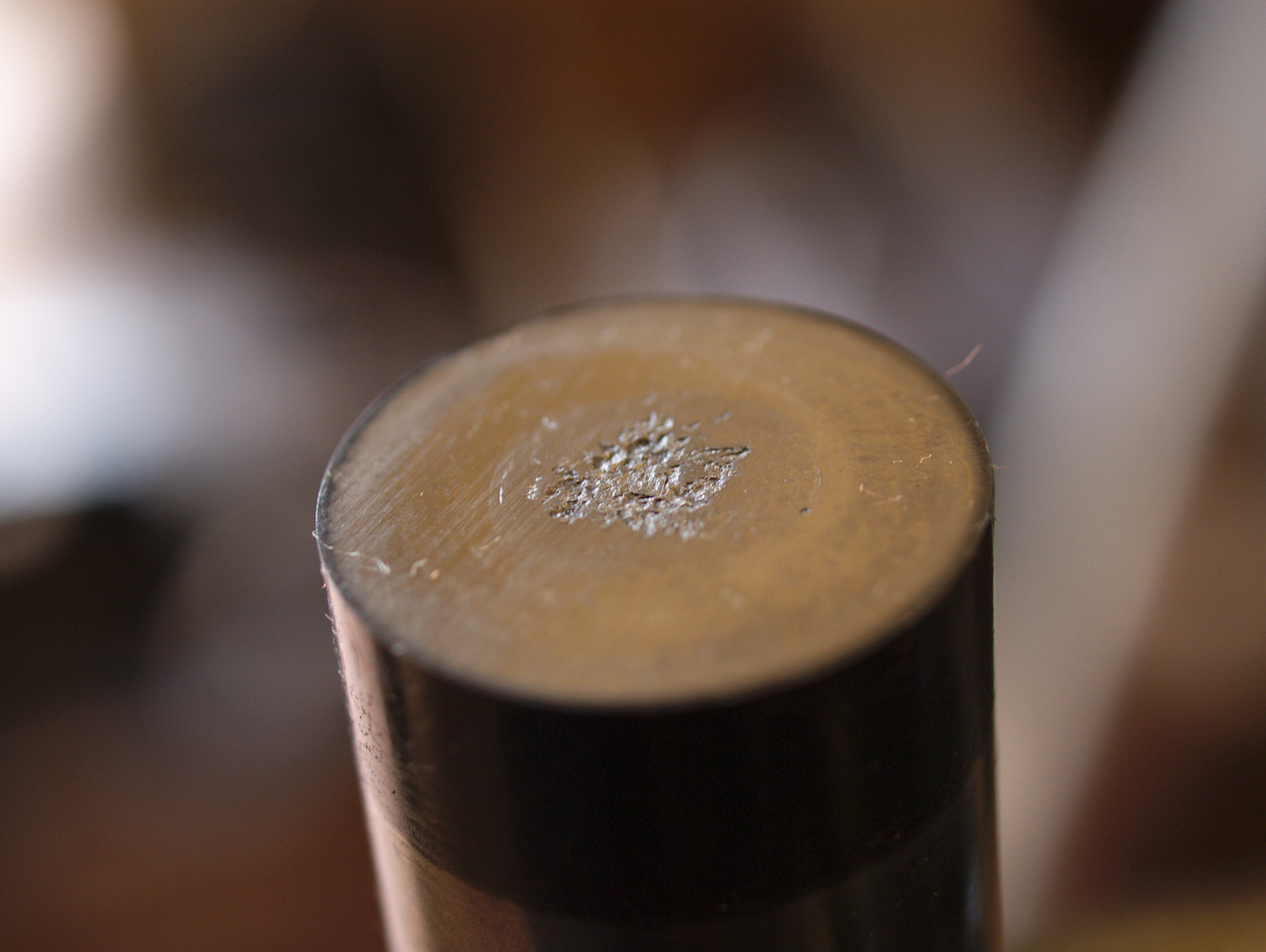
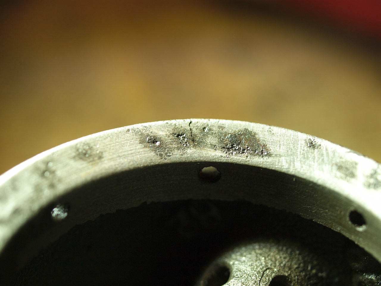
Gonna go out on a limb here and say that's not right clever, for the running surface of a lifter. The cam lobe looks flawless, though. This is the lifter for that stuck valve, which may possibly be part of its issues? The lifter for the intake valve of that cylinder is absolutely fine, so I don't think it's caused by running without the load of pushrod & valve spring...
So that'll need investigating & sorting. After that, I'd run out of excuses; time to play executioner...
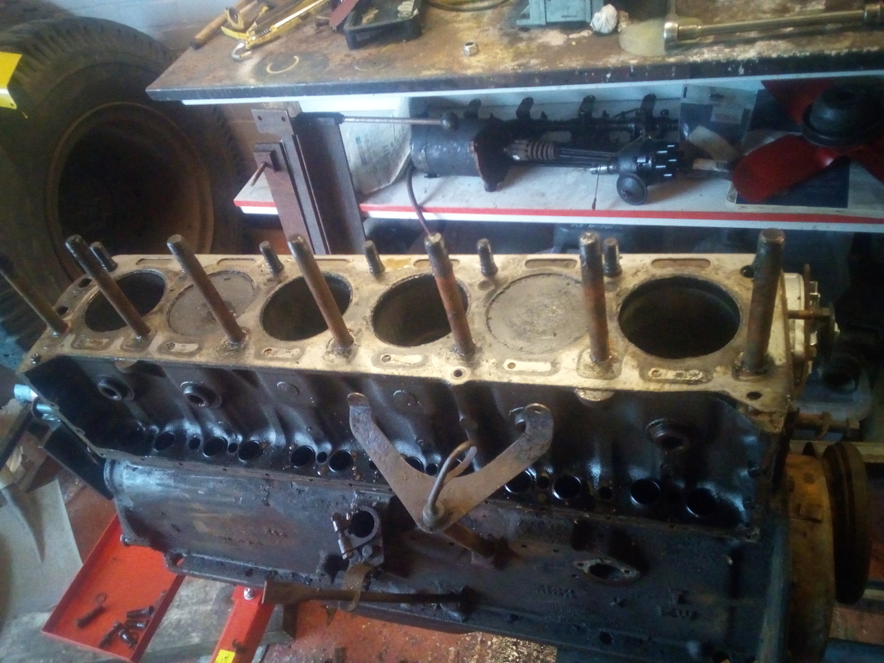
Off with her head!
More surprises: Number 4 piston looks like it's had some excitement in the past!
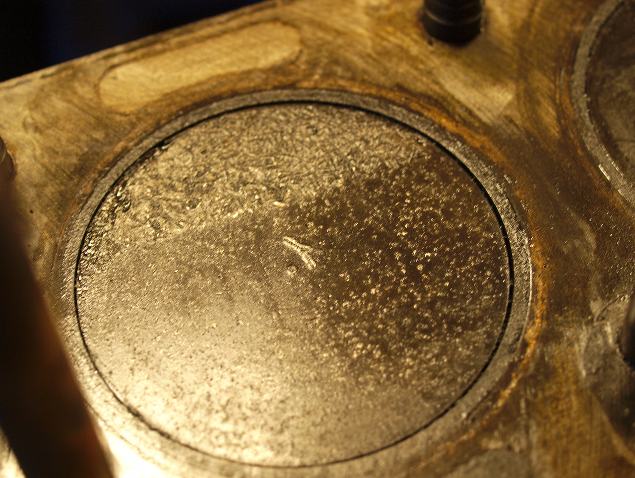
But it doesn't seem like this head has seen any of it. (Though this appears to have also been the cylinder that has been sat with the inlet valve open while the truck was in the breaker's yard, since it shows signs of corrosion; nothing too worrying, though.)
And, of course, there was the non-surprise of confirming that the exhaust valve on number 2 is stuck. Doesn't seem to be bent, at first glance, but I've not done a detailed inspection.
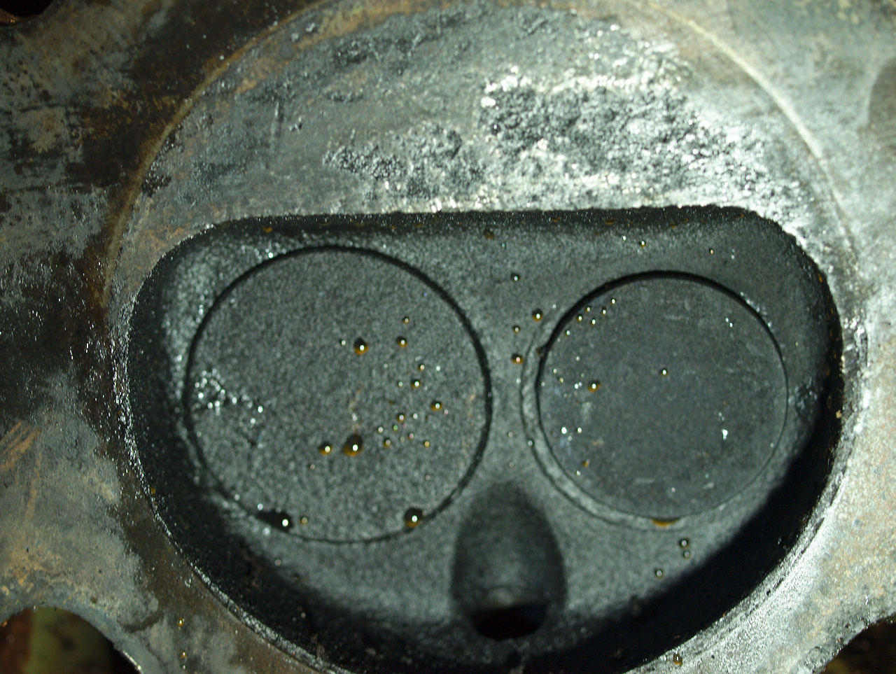
And, since I can now measure one of those chambers...
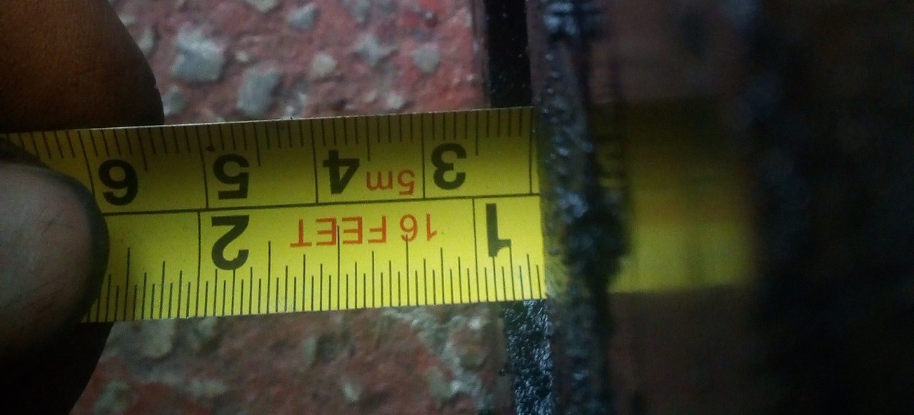
Apparently I don't have a more accurate measuring tool than a tape
measure up at the unit, but still... near enough 20mm deep from the
face of the head, to the top of the chamber.
ANd that left us here, tonight:
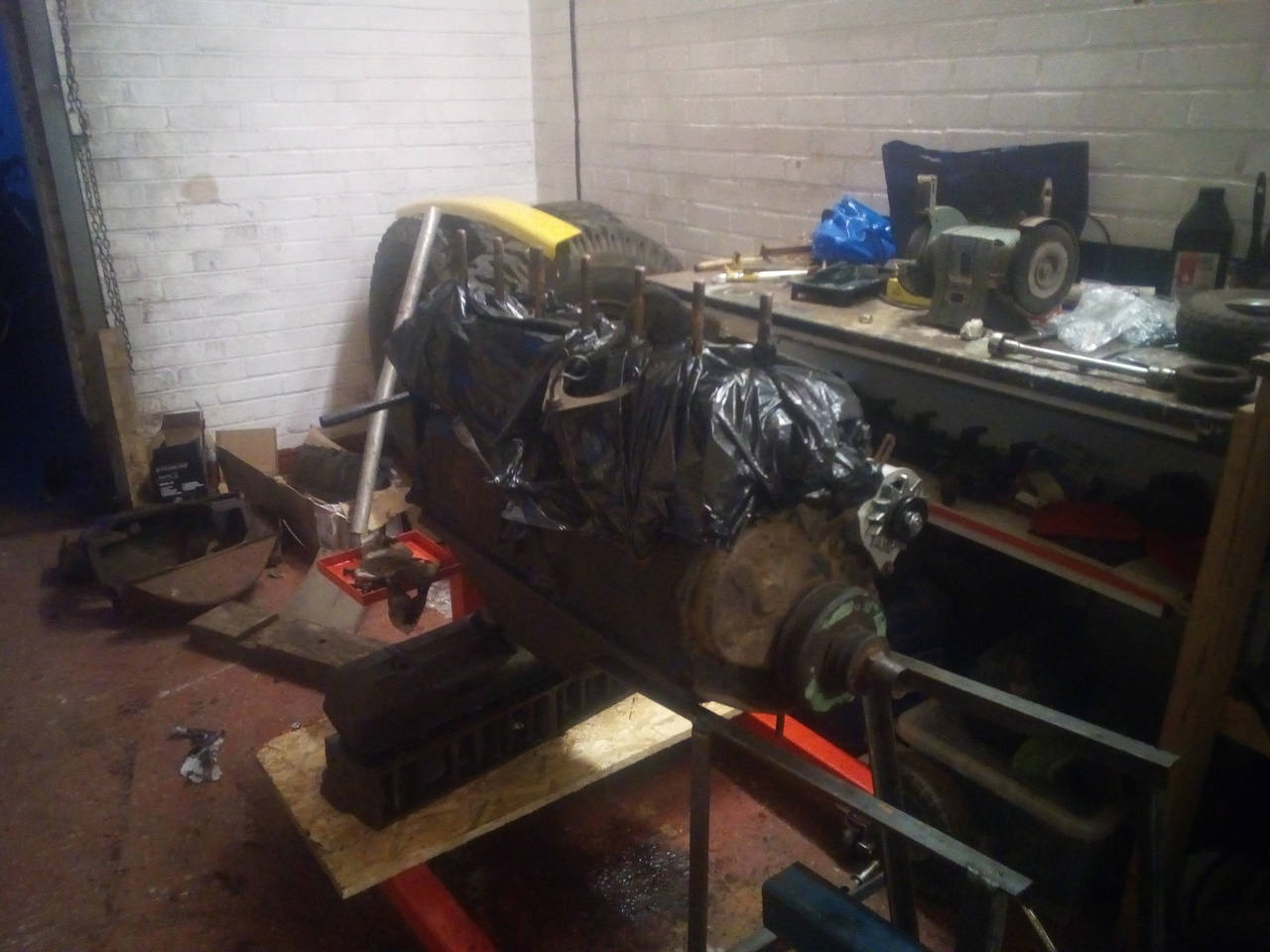
Block oiled up, and under plastic to keep any grinding dust and other detritus out. I should probably shift focus back to the compressor, get that back together then I have fewer pieces knocking around to get broken/lost. Plus, then it's one more thing I can tick off being done!
28 Nov 2019
Amazingly, I did a progress today. (Honest, I did! ...Okay, it's technically yesterday, now, but same difference.)
Step the first: Extract the oil control ring & retaining clip from that NOS piston, to fit to the old piston...
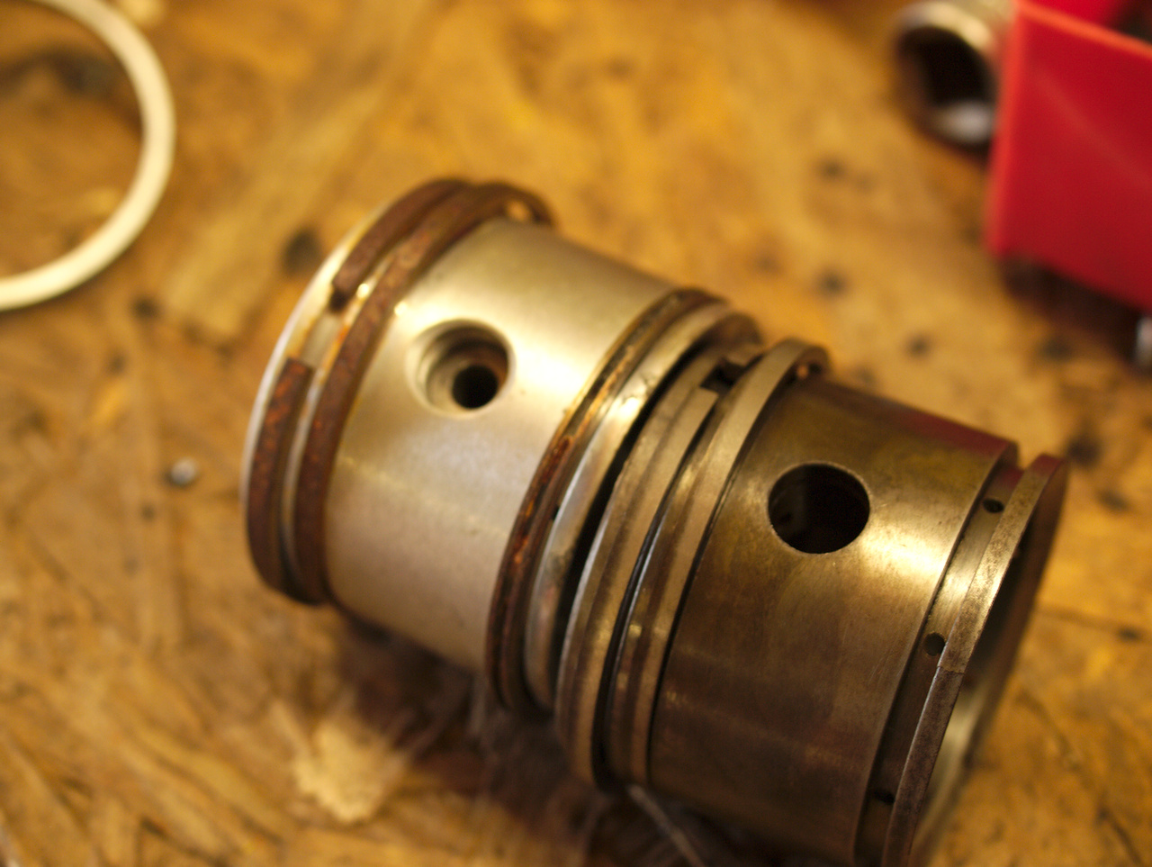
Can you see the problem yet? I hadn't, at this point!
Okay, extract the ring and then clean the surface rust off, easy enough
Mm. That's not good; guess I'm fitting the whole NOS aluminium piston, since the original cast-iron one is cracked. Not sure when that happened, but it might be why the original oil-control ring snapped when I went to remove it. Who knows. New rings filed, piston fitted to rod and dropped into the hole. Fits quite nice. Should probably pop it back out and give the bore a quick hone just to help the rings seat, which isn't really a problem, it's not all torqued up yet since I didn't have the spec to hand.
At some point my steel order turned up, and I added reinforcing to the engine stand, and then...
Engine wants belly-rubs!
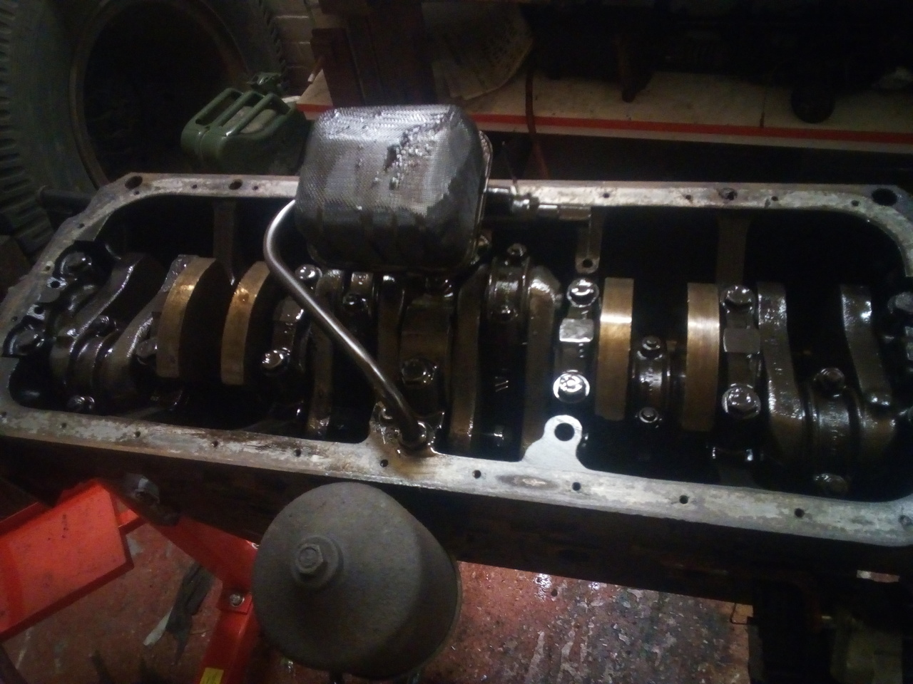
Looking good in there!
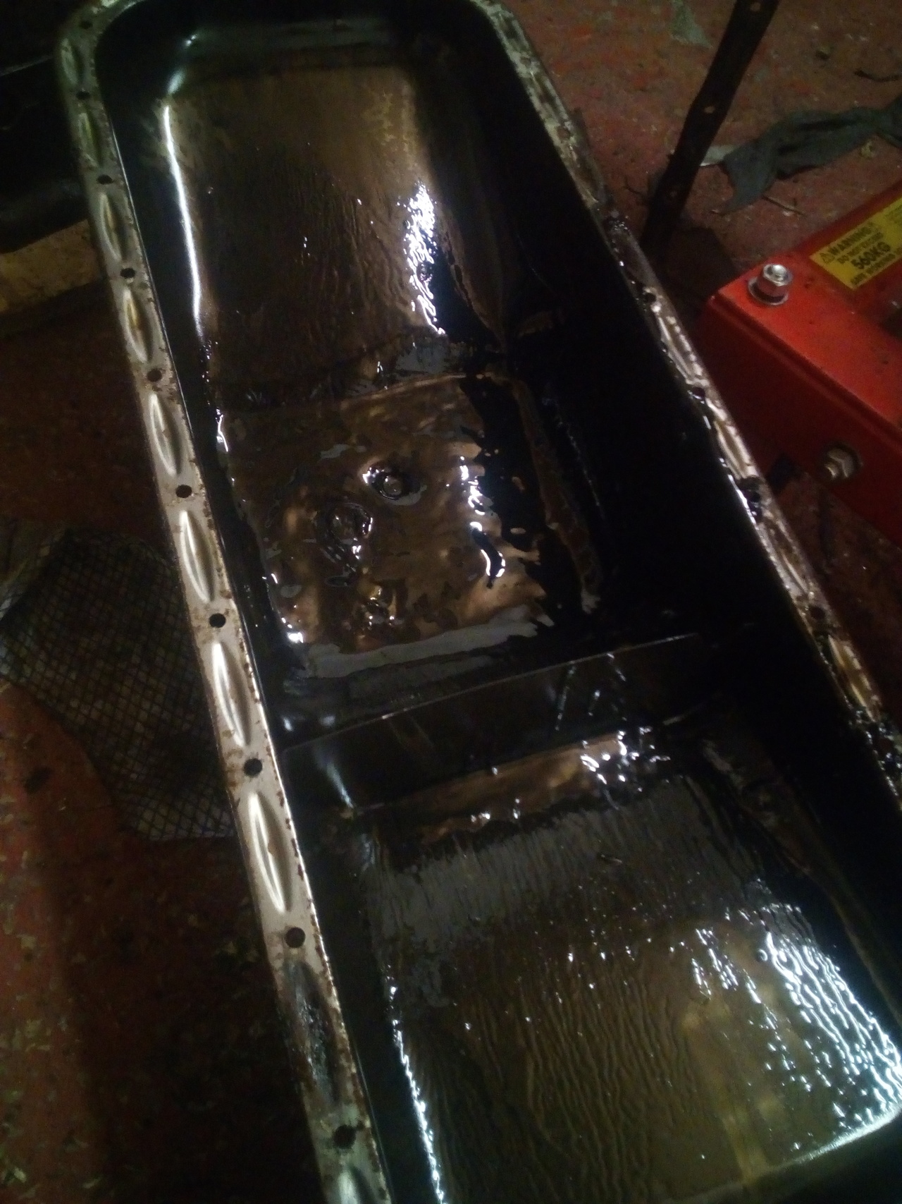
And not all that bad in there, either! Only quarter of an inch of sludge at the bottom of the sump!
Spent the rest of the evening cleaning out the inside of the sump back to nearly spotless, and hammering out the dents, since the sump appears to have met the front diff at some point.
Frankenhealey said: Usually that means 'DBS' or Driven by Squaddies, or Destroyed by Squaddies in the worst case.
Interestingly, Richard Farrant on HMVF has noted that I've got the wrong sump. The 4x4s are supposed to have a front-sump, which gives more clearance to the diff, and also a sump guard to make it marginally more difficult for aforementioned squaddie to rip it right off on something.
That would explain the diff-print in the sump, then.